Difference between revisions of "VTube-LASER Cut Planes"
(→How to Create a Cut Plane) |
(→Other Pages) |
||
| Line 119: | Line 119: | ||
</tr> | </tr> | ||
</table> | </table> | ||
| + | |||
| + | |||
| + | ==Diagnosing Problems== | ||
| + | |||
| + | It has been our experience that there are two conditions where the Cut Plane is likely to fail to work properly: | ||
| + | |||
| + | * If the wrong ball probe is selected in the FARO probe compensation menu, then the cut plane may fail. | ||
| + | <br> | ||
| + | * If the ball probe was never calibrated, or is not calibrated properly, then the cut plane has a VERY HIGH chance of failing. We have seen Cut Plane issues that are tied back to this problem.<br><br> | ||
| + | |||
| + | |||
==Other Pages== | ==Other Pages== | ||
*Back to the [[VTube-LASER]] page | *Back to the [[VTube-LASER]] page | ||
Revision as of 00:25, 5 September 2015
|
About Cut Planes
Cut planes allow VTube-LASER to define a plane of a table or other surface in order to cut laser points from being used in measurements to VTube-LASER.
|
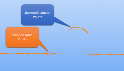
Without the Cut Plane Offset set properly, scanning data from a cylinder on a table would appear like this to VTube-LASER. |
|
|
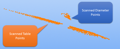
We can use orbit to tilt the view slightly. You can see how the table points are included in this scan of an outer diameter. |
|
|
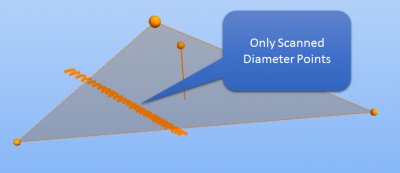
Increase the Cut Plane offset and you will remove all outliers from the table surface. |
How to Create a Cut Plane
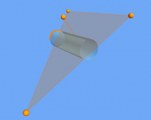
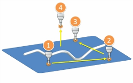
Cut planes are created with four measurements with the ball probe.
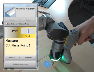
STEP 1In VTube-LASER click on Measure Process, then click on Measure Cut Plane. The Laser scanner will turn off automatically. |
|
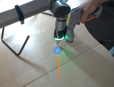
STEP 2Move the probe to another place on table. The further away from the first point, the better for the math engine. |
|
|
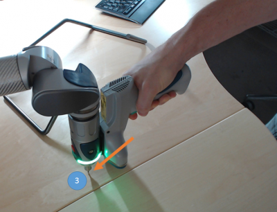
STEP 3Move the probe to another place on table in a way that forms an approximate equilateral triangle. (It is best to not make the triangle a thin sliver triangle. |
|
|
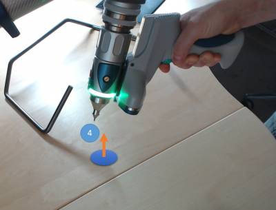
STEP 4Move the probe anywhere above the table. This forms the up direction of the plane (also called the "normal" to the plane) |
|
STEP 5The Cut Plane Offset menu will display. Granite Surface Plate0.039" offset is acceptable Office Tables0.125" offset is usually acceptable (Tables are much less flat than surface plates - so the offset needs to be greater than on surface plates.) Offset Distance Rule
|
Diagnosing Problems
It has been our experience that there are two conditions where the Cut Plane is likely to fail to work properly:
- If the wrong ball probe is selected in the FARO probe compensation menu, then the cut plane may fail.
- If the ball probe was never calibrated, or is not calibrated properly, then the cut plane has a VERY HIGH chance of failing. We have seen Cut Plane issues that are tied back to this problem.
Other Pages
- Back to the VTube-LASER page
