Difference between revisions of "How to Reverse Engineer with Split Bend"
(→STEP 6: Copy Measured to Master) |
(→STEP 4: Configure the Measure Setup) |
||
| (70 intermediate revisions by one user not shown) | |||
| Line 12: | Line 12: | ||
</table> | </table> | ||
| − | + | __NOTOC__ | |
| − | == How to Reverse Engineer Using Split Bend == | + | == How to Reverse Engineer a Part Using Split Bend == |
<table cellpadding=10 width="900"> | <table cellpadding=10 width="900"> | ||
<tr valign=top> | <tr valign=top> | ||
| − | <td width= | + | <td width=500 > |
The Split Bend feature allows you to accurately measure bends that equal or exceed 180 degrees.<br><br> | The Split Bend feature allows you to accurately measure bends that equal or exceed 180 degrees.<br><br> | ||
Split Bend setup is controlled in the Bend Setup tab of the Master Tube menu in VTube-LASER, and in the Bend Setup tab in VTube-STEP. Both modes of VTube allow you to configure Split Bends.<br><br> | Split Bend setup is controlled in the Bend Setup tab of the Master Tube menu in VTube-LASER, and in the Bend Setup tab in VTube-STEP. Both modes of VTube allow you to configure Split Bends.<br><br> | ||
To turn a Split Bend ON for a straight section, you enter the Split Bend window and select the straights that should be treated as Split Bends.<br><br> | To turn a Split Bend ON for a straight section, you enter the Split Bend window and select the straights that should be treated as Split Bends.<br><br> | ||
| + | </td> | ||
| + | <td> | ||
| + | [[image:vtube-laser_v2.2_master_with_splitbend.png|500px]] | ||
</td> | </td> | ||
</tr> | </tr> | ||
| Line 29: | Line 32: | ||
<tr valign=top> | <tr valign=top> | ||
<td width=400 > | <td width=400 > | ||
| − | Enter the Part Setup data for the new part. Especially enter the DEFAULT RADIUS. (You can measure the radius if necessary in Measure Process.) | + | Enter the Part Setup data for the new part. Especially enter the PART NUMBER and DEFAULT RADIUS. (You can measure the radius if necessary in Measure Process.) |
</td> | </td> | ||
<td width=400 > | <td width=400 > | ||
| Line 46: | Line 49: | ||
</td> | </td> | ||
<td width=400 > | <td width=400 > | ||
| − | [[image:vtube- | + | [[image:vtube-laser_v4_set_master_point_count.png|500px]] |
</td> | </td> | ||
</tr> | </tr> | ||
</table> | </table> | ||
| − | |||
==STEP 3: Configure the Split Bend Window== | ==STEP 3: Configure the Split Bend Window== | ||
| Line 59: | Line 61: | ||
</td> | </td> | ||
<td width=400 > | <td width=400 > | ||
| − | [[image:vtube- | + | [[image:vtube-laser_v4_enter_split_bend_window.png|500px]]<br> |
</td> | </td> | ||
</tr> | </tr> | ||
| Line 68: | Line 70: | ||
</td> | </td> | ||
<td width=400 > | <td width=400 > | ||
| − | [[image:vtube- | + | [[image:vtube-laser_v4_split_bend_window_straight_selected1.png|500px]] |
</td> | </td> | ||
</tr> | </tr> | ||
</table> | </table> | ||
| + | ==STEP 4: Configure the Measure Setup== | ||
| + | <table cellpadding=10 width="900"> | ||
| + | <tr valign=top> | ||
| + | <td width=400 > | ||
| + | Configure Measure Setup like this:<br><br> | ||
| + | # Press the Measure Setup button in the Navigation pane.<br><br> | ||
| + | # Press the Laser tab if it is not active.<br><br> | ||
| + | # Activate the LASER scanner for Split Bends.<br><br> | ||
| + | # Set the number of allowed STRIPES to 50 for Split Bends.<br><br> | ||
| + | </td> | ||
| + | <td width=400 > | ||
| + | [[image:vtube-laser_v4_lasersetup_splitbends.png|500px]]<br> | ||
| + | </td> | ||
| + | </tr> | ||
| + | <tr valign=top> | ||
| + | <td width=400 > | ||
| + | Continue with the Measure Setup in the Separation Filter menu<br><br> | ||
| + | # Press the Separation Filter tab.<br><br> | ||
| + | # Set the SPLIT BEND Scan Type to DISTANCE.<br><br> | ||
| + | # Set the SPLIT BEND Scan Distance to 0.015" (or .38 mm). <br><br> | ||
| + | </td> | ||
| + | <td width=400 > | ||
| + | [[image:vtube-laser_v4_separationsetup_splitbend.png.png|500px]] | ||
| + | </td> | ||
| + | </tr> | ||
| + | </table> | ||
| − | ==STEP | + | ==STEP 5: Measure The Part== |
<table cellpadding=10 width="900"> | <table cellpadding=10 width="900"> | ||
<tr valign=top> | <tr valign=top> | ||
<td width=400 > | <td width=400 > | ||
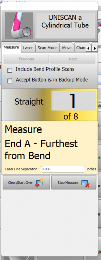
This step is identical to regular reverse-engineering measuring.<br><br> | This step is identical to regular reverse-engineering measuring.<br><br> | ||
| − | Press FINISH and | + | When you arrive at the split bend to scan, VTube-LASER will make a special sound and tell you to scan the OUTSIDE of the bend. Scan as much data as you want - up to 250 stripes. The goal is to be sure that at least one point in one of the stripes touches the highest point of the outside of the bend. So you can take as many stripes of data as you want - VTube will take them all in without a problem.<br><br> |
| + | During scanning, release the green button, and look at the screen. You should see a large area of surfaces that pass the point of the outside of the bend. Press the RED button if you are finished scanning the outside and have not come to 250 stripes.<br><br> | ||
| + | Now scan the center of the inside. Be sure that at least one point in one stripe passes the center inside of the bend. If you are not sure, then release the green button and look at the screen to see if you have points and surfaces that appear to be in the right place. If you know you've scanned the center, then press the RED button to move on to the next straight.<br><br> | ||
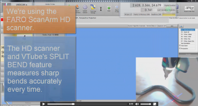
| + | '''If you want to see a Split Bend measurement then see video 40 in [[VTube-LASER_Videos]].'''<br><br> | ||
| + | [[image:vtube-laser_v2.2-splitbendvideo40.png|400px|link=VTube-LASER Videos]]<br><br> | ||
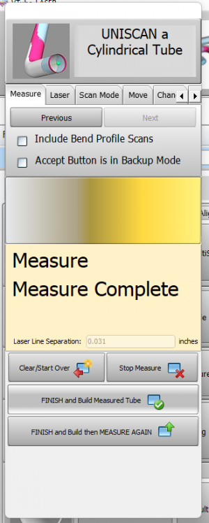
| + | Press FINISH and Build Measured Tube when the measurement is completed. | ||
</td> | </td> | ||
<td width=400 > | <td width=400 > | ||
| − | [[image:vtube-laser- | + | [[image:vtube-laser-v4_measureguide_cylindricaltube.png|200px]]<br><br> |
</td> | </td> | ||
</tr> | </tr> | ||
</table> | </table> | ||
| + | <br><br> | ||
| + | ==STEP 6: Choose Build Measured Tube Data Only== | ||
| + | <table cellpadding=10 width="900"> | ||
| + | <tr valign=top> | ||
| + | <td width=400 > | ||
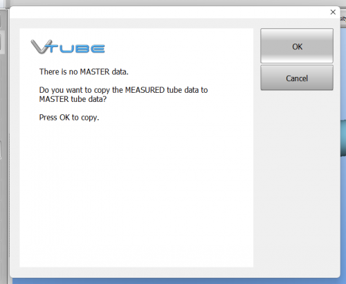
| + | FINISH and Build Measured Tube and press okay when the next popup screen appears. This is asking users to verify they want to make the tube they just measured the new MASTER tube going forward. <br><br> | ||
| + | |||
| + | |||
| + | [[image:vtube-laser_v4_copy.png|300px]]<br> | ||
| − | |||
<table cellpadding=10 width="900"> | <table cellpadding=10 width="900"> | ||
<tr valign=top> | <tr valign=top> | ||
<td width=400 > | <td width=400 > | ||
| − | |||
| − | |||
| − | |||
</td> | </td> | ||
<td width=400 > | <td width=400 > | ||
| − | [[image:vtube- | + | [[image:vtube-laser_v4_master.png|500px]]<br> |
</td> | </td> | ||
</tr> | </tr> | ||
| + | </table> | ||
| + | |||
| + | ==STEP 7: Copy Measured to Master== | ||
| + | <table cellpadding=10 width="900"> | ||
<tr valign=top> | <tr valign=top> | ||
<td width=400 > | <td width=400 > | ||
| − | + | Copy Measured to Master Data in the Data Handling menu. This will overwrite the MASTER data ZEROS with the MEASURED tube data. <br><br> | |
| + | When you press this button, the MEASURED data will be copied to the MASTER data menu and the MASTER data menu will display automatically. | ||
</td> | </td> | ||
<td width=400 > | <td width=400 > | ||
| − | [[image:vtube- | + | [[image:vtube-laser_v4_copy_measured_to_master1.png|500px]]<br> |
</td> | </td> | ||
</tr> | </tr> | ||
</table> | </table> | ||
| + | ==STEP 8: Optional Reset Origin to Zero== | ||
| + | <table cellpadding=10 width="900"> | ||
| + | <tr valign=top> | ||
| + | <td width=400 > | ||
| + | Some customers prefer to translate the new MASTER data so that the first point is at 0,0,0. | ||
| + | </td> | ||
| + | <td width=400 > | ||
| + | [[image:vtube-laser_v4_reset_origin_to_zero.png|500px]]<br> | ||
| + | </td> | ||
| + | </tr> | ||
| + | </table> | ||
| + | |||
| + | ==STEP 9: View the New Master Tube== | ||
| + | <table cellpadding=10 width="900"> | ||
| + | <tr valign=top> | ||
| + | <td width=400 > | ||
| + | View the new MASTER tube by switching the display of the Master tube on, then redrawing and zooming all.<br><br> | ||
| + | In this case, the MASTER tube is translated in space from the measured tube because the coordinates were zeroed in the previous step. | ||
| + | </td> | ||
| + | <td width=400 > | ||
| + | [[image:vtube-laser_v2.2-copy_to_master_from_measured_redraw.png|500px]]<br> | ||
| + | </td> | ||
| + | </tr> | ||
| + | </table> | ||
| + | |||
| + | ==STEP 10: Optional Alignment Test== | ||
| + | <table cellpadding=10 width="900"> | ||
| + | <tr valign=top> | ||
| + | <td width=400 > | ||
| + | This is a cross-check to be sure the process was performed properly. Enter the Inspection Results menu, and press Recalculate for the alignment.<br><br> | ||
| + | Since VTube is aligning a part to itself, the deviations should be exactly zero. | ||
| + | </td> | ||
| + | <td width=400 > | ||
| + | [[image:vtube-laser_v2.2-recalculate_alignment_perfect_match_180.png|500px]]<br> | ||
| + | </td> | ||
| + | </tr> | ||
| + | </table> | ||
| − | ==STEP | + | ==STEP 11: Save the VTube Project== |
<table cellpadding=10 width="900"> | <table cellpadding=10 width="900"> | ||
<tr valign=top> | <tr valign=top> | ||
<td width=400 > | <td width=400 > | ||
| − | + | Press the Project Save button in the Toolbar, choose the project save path and filename, and save the VTube Project file. | |
</td> | </td> | ||
<td width=400 > | <td width=400 > | ||
| − | [[image:vtube- | + | [[image:vtube-laser_v4-SaveProjects.png|500px]]<br> |
</td> | </td> | ||
</tr> | </tr> | ||
Latest revision as of 19:58, 16 December 2022
|
How to Reverse Engineer a Part Using Split Bend
|
The Split Bend feature allows you to accurately measure bends that equal or exceed 180 degrees. |
STEP 1: Enter PART SETUP Data
|
Enter the Part Setup data for the new part. Especially enter the PART NUMBER and DEFAULT RADIUS. (You can measure the radius if necessary in Measure Process.) |
STEP 2: Populate the MASTER TUBE DATA Grid
|
Since the Split Bend feature creates a grid based on the number of straights in the MASTER data, it is important to set the number of points that you will be measuring in the reversed tube. |
STEP 3: Configure the Split Bend Window
|
The Split Bend window is on the Bend Setup tab in the MASTER TUBE menu. Click into that window. |
|
|
In the Split Bend window, set any straight that will be treated as a Split Bend. |
STEP 4: Configure the Measure Setup
|
Configure Measure Setup like this:
|
|
|
Continue with the Measure Setup in the Separation Filter menu
|
STEP 5: Measure The Part
|
This step is identical to regular reverse-engineering measuring. |
STEP 6: Choose Build Measured Tube Data Only
|
FINISH and Build Measured Tube and press okay when the next popup screen appears. This is asking users to verify they want to make the tube they just measured the new MASTER tube going forward. STEP 7: Copy Measured to Master
STEP 8: Optional Reset Origin to Zero
STEP 9: View the New Master Tube
STEP 10: Optional Alignment Test
STEP 11: Save the VTube Project
Other Pages
|
