Difference between revisions of "How to Reverse Engineer with Split Bend"
(→STEP 7: Optional Reset Origin to Zero) |
(→STEP 8: View the New Master Tube) |
||
| Line 149: | Line 149: | ||
<td width=400 > | <td width=400 > | ||
[[image:vtube-laser_v2.2-copy_to_master_from_measured_redraw.png|500px]]<br> | [[image:vtube-laser_v2.2-copy_to_master_from_measured_redraw.png|500px]]<br> | ||
| + | </td> | ||
| + | </tr> | ||
| + | </table> | ||
| + | |||
| + | |||
| + | ==STEP 9: Optional Alignment Test== | ||
| + | <table cellpadding=10 width="900"> | ||
| + | <tr valign=top> | ||
| + | <td width=400 > | ||
| + | This is a cross-check to be sure the process was performed properly. Enter the Inspection Results menu, and press Recalculate for the alignment.<br><br> | ||
| + | Since VTube is aligning a part to itself, the deviations should be perfectly zero. | ||
| + | </td> | ||
| + | <td width=400 > | ||
| + | [[image:vtube-laser_v2.2-recalculate_alignment_perfect_match_180.png|500px]]<br> | ||
</td> | </td> | ||
</tr> | </tr> | ||
Revision as of 01:34, 4 February 2016
|
How to Reverse Engineer Using Split Bend
|
The Split Bend feature allows you to accurately measure bends that equal or exceed 180 degrees. |
STEP 1: Enter PART SETUP Data
|
Enter the Part Setup data for the new part. Especially enter the DEFAULT RADIUS. (You can measure the radius if necessary in Measure Process.) |
STEP 2: Populate the MASTER TUBE DATA Grid
|
Since the Split Bend feature creates a grid based on the number of straights in the MASTER data, it is important to set the number of points that you will be measuring in the reversed tube. |
STEP 3: Configure the Split Bend Window
|
The Split Bend window is on the Bend Setup tab in the MASTER TUBE menu. Click into that window. |
|
|
In the Split Bend window, set any straight that will be treated as a Split Bend. |
STEP 4: Measure The Part
|
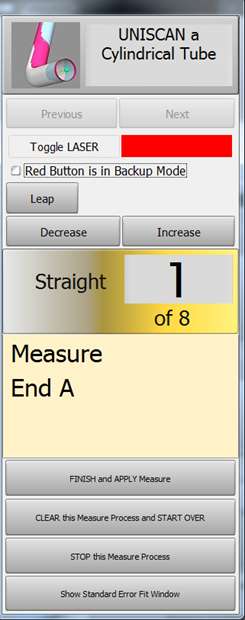
This step is identical to regular reverse-engineering measuring. |
STEP 5: Choose Build Measured Tube Data Only
|
Because the MASTER data row count is greater than zero, the Measurement Complete window will offer to allow you to ALIGN the measured tube. |
|
|
The new measured tube will appear as a blue tube like this. |
STEP 6: Copy Measured to Master
|
Copy Measured to Master Data in the Data Handling menu. This will overwrite the MASTER data ZEROS with the MEASURED tube data. |
STEP 7: Optional Reset Origin to Zero
|
Some customers prefer to translate the new MASTER data so that the first point is at 0,0,0. |
STEP 8: View the New Master Tube
|
View the new MASTER tube by switching the display of the Master tube on, then redrawing and zooming all. |
STEP 9: Optional Alignment Test
|
This is a cross-check to be sure the process was performed properly. Enter the Inspection Results menu, and press Recalculate for the alignment. |
Other Pages
- Back to VTube-LASER
- See also Calibration-Leapfrog-Move Targets
- Purchase the targets at the store.


