|
|
| Line 36: |
Line 36: |
| | | | |
| | | | |
| − | <td align="center"><div align="center"><font face="Verdana, Arial, Helvetica, sans-serif"><a href="dxf_layer_dialog.jpg"><img src="dxf_layer_dialog_150.jpg" width="150" height="154" alt="" border="0"></a></font></div></td>
| + | ===OUTPUT DATA OPTIONS=== |
| − | </tr>
| + | <table width=600> |
| − | <tr>
| + | <tr> |
| − | <td><p><font size="4" face="Verdana, Arial, Helvetica, sans-serif"><strong>SUPRAVISION DATA OPTIONS</strong></font></p>
| + | <td> |
| − | <blockquote>
| + | The converter allows further control of the output data during conversion: |
| − | <p><font face="Verdana, Arial, Helvetica, sans-serif"><br>
| + | *. Part Number |
| − | DXF2SV allows further control of the following internal Supravision data
| + | *. Diameter |
| − | during conversion:
| + | *. Total Length</font> |
| − | </font></p>
| + | </td> |
| − | <blockquote>
| + | <td> |
| − | <p><font face="Verdana, Arial, Helvetica, sans-serif">1. Part Number<br>
| + | [[image:acad2bender_outputoptions.jpg|200px]] |
| − | 2. Diameter<br>
| + | </td> |
| − | 3. Total Length</font></p>
| + | </tr> |
| − | </blockquote>
| + | </table> |
| − | </blockquote></td>
| + | |
| − | <td><div align="center"><a href="./supravision_conversion_setup.jpg"><img src="./supravision_conversion_setup_250.jpg"></a></div></td>
| + | |
| − | </tr>
| + | |
| − | <tr>
| + | |
| | <td><p><font size="4" face="Verdana, Arial, Helvetica, sans-serif"><strong>AUTOMATIC PROCESSING</strong></font></p> | | <td><p><font size="4" face="Verdana, Arial, Helvetica, sans-serif"><strong>AUTOMATIC PROCESSING</strong></font></p> |
| | <blockquote> | | <blockquote> |
Revision as of 17:44, 2 June 2009
AutoCAD to Bender software, also known as DXF2SV, converts data from AutoCAD DXF files to bender compatible Supravision files.
Software Features
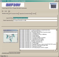
SETUP IMPORT / EXPORT FILES
| Enter the IMPORT DXF file and the new EXPORT Supravision file. |
 |
RECOGNIZES AUTOCAD GEOMETRY
|
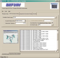
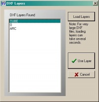
The centerline data that defines the tube shape can be placed on any unique AutoCAD layer. The program recognizes 3-D lines on a designated search layer that define the end points and intersection points. (The search layer is programmable.) 3-D arcs on that layer (or another unique layer) are used to determine the centerline bend radii at each bend. The program also allows you to skip using 3-D arcs in order to build programs with a default radius. The Centerline Search Layer dialog allows you to select the search layer from a list of layers available in the current DXF file. |
 |
PROGRAMMABLE INTERSECTION TOLERANCE
|
A programmable intersection tolerance ensures that intersecting lines are matched using the DXF2KEINS matching algorithm - even if rounding errors exist in the data. With this feature, it is possible to have geometry that is just "close" (not perfect) and the DXF2SV converter will still be able to build the centerline data.
|

|
OUTPUT DATA OPTIONS
|
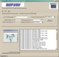
The converter allows further control of the output data during conversion:
- . Part Number
- . Diameter
- . Total Length</font>
|
<td>
 </td>
</td>
</table>
<td>AUTOMATIC PROCESSING
The program can be run in automode, which allows for control by other programs.
In this mode, DXF2SV automatically unloads when conversion is complete.
</td>
<td></td>
   </tr>
   <tr>
<td>CONVERSION LOG
During conversion, DXF2SV displays a conversion log on the screen to indicate
the progress of the build. Also, it builds a conversion log file that
enables you to track the last session results in any word processor.
The log contains a date/time stamp for every line built.
</td>
<td></td>
   </tr>
   <tr>
<td>SUPRAVSION DATA LOG
After conversion, DXF2SV displays the created Supravision data that was
saved to the newly built Supravision data file. This log is created in
the Rich Edit format and can be viewed by WordPad or most other Rich
Edit compatible word processors.
</td>
<td><a href="./supravision_data_log_682.jpg"><img src="./supravision_data_log_373.jpg" align="right" width=250 height=125></a>
</td>
   </tr>
   </table>
   DXF2SV Program
 Features
SETUP IMPORT / EXPORT FILES
Enter the IMPORT DXF file and the new EXPORT Supravision file.
|
<a href="./filename_setup.jpg"><img
src="./filename_setup_250.jpg"></a> |
RECOGNIZES AUTOCAD GEOMETRY
The centerline data that defines the tube shape can be placed on any unique
AutoCAD layer.
The program recognizes 3-D lines on a designated search layer that
define the end points and intersection points. (The search layer is
programmable.)
3-D arcs on that layer (or another unique layer) are used to determine
the centerline bend radii at each bend. The program also allows you
to skip using 3-D arcs in order to build programs with a default radius.
The Centerline Search Layer dialog allows you to select the search
layer from a list of layers available in the current DXF file.
|
<a href="./dxf_conversion_setup.jpg"><img src=
"./dxf_conversion_setup_250.jpg"></a> |
INTERSECTION
TOLERANCE
A programmable intersection tolerance ensures that intersecting lines
are matched using the DXF2KEINS matching algorithm - even if rounding
errors exist in the data. With this feature, it is possible to have
geometry that is just "close" (not perfect) and the DXF2SV
converter will still be able to build the centerline data.
|
<a href="dxf_layer_dialog.jpg"><img src="dxf_layer_dialog_150.jpg" width="150" height="154" alt="" border="0"></a> |
SUPRAVISION DATA OPTIONS
DXF2SV allows further control of the following internal Supravision data
during conversion:
1. Part Number
2. Diameter
3. Total Length
|
<a href="./supravision_conversion_setup.jpg"><img src="./supravision_conversion_setup_250.jpg"></a> |
AUTOMATIC PROCESSING
The program can be run in automode, which allows for control by other programs.
In this mode, DXF2SV automatically unloads when conversion is complete.
|
|
CONVERSION LOG
During conversion, DXF2SV displays a conversion log on the screen to indicate
the progress of the build. Also, it builds a conversion log file that
enables you to track the last session results in any word processor.
The log contains a date/time stamp for every line built.
|
|
SUPRAVSION DATA LOG
After conversion, DXF2SV displays the created Supravision data that was
saved to the newly built Supravision data file. This log is created in
the Rich Edit format and can be viewed by WordPad or most other Rich
Edit compatible word processors.
|
<a href="./supravision_data_log_682.jpg"><img src="./supravision_data_log_373.jpg" align="right" width=250 height=125></a> |


