Difference between revisions of "VTube-LASER Cut Planes"
From ATTWiki
(→STEP 1) |
(→STEP 2) |
||
| Line 41: | Line 41: | ||
===STEP 2=== | ===STEP 2=== | ||
| − | Press | + | Move the probe to another place on table. The further away from the first point, the better for the math engine.<br><br> |
| + | Press and release the green button.</td> | ||
<td> | <td> | ||
| − | [[image:vtube- | + | [[image:vtube-laser_cutplane_step1.png|400px]] |
</td> | </td> | ||
</tr> | </tr> | ||
Revision as of 22:20, 4 September 2015
|
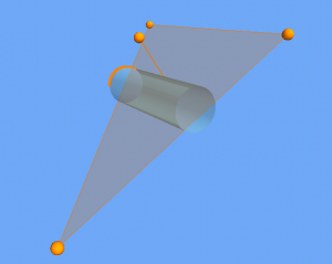
About Cut Planes
Cut planes allow VTube-LASER to define a plane of a table or other surface in order to cut laser points from being used in measurements to VTube-LASER.
How to Create a Cut Plane
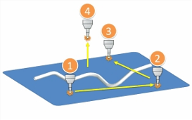
Cut planes are created with four measurements with the ball probe.
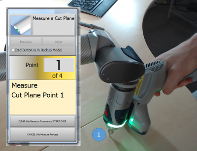
STEP 1In VTube-LASER click on Measure Process, then click on Measure Cut Plane. The Laser scanner will turn off automatically. |
|
STEP 2Move the probe to another place on table. The further away from the first point, the better for the math engine. |
|
STEP 3Select the correct ball probe then press OK. |
|
STEP 4Press the Close button in the FARO Arm Utilities window. |
|
STEP 5Observe that the new ball probe selection will appear in the Arm grid. |
Other Pages
- Back to the VTube-LASER page


