Difference between revisions of "VTube Communication for UNISON Benders"
(→STEP 1 - Bend the Tube) |
(→STEP 2 - Measure the tube with VTube-LASER) |
||
| Line 268: | Line 268: | ||
<td> | <td> | ||
| − | [[image:VTube-LASER | + | [[image:VTube-LASER UNISON Inspection Result.png|400px]] |
</td> | </td> | ||
</tr> | </tr> | ||
Revision as of 22:53, 11 February 2018
|
This page describes the use of the VTube to UNISON Supravision file communications. Descriptions for VTube-STEP and VTube-LASER are included. |
Protocol
|
VTube-STEP can send data directly to the UNISON LTD software YBC values. |
UNISON CONTROL SETUP
|
The connection uses a standard network connection between Windows computers. You will need to attach the UNISON bender to a standard network to allow this kind of communication. YBC --> Supravision ScreenThe Supravision screen in is where all communications occur. You can press the measuring center button in the YBC screen to load the Supravision screen. Bender NumberThe Supravision Network protocol requires that the bender number at the control match the bender number in VTube-LASER. so, it is important to know what bender number is being used for this bender in the VTube setup. (Make the two numbers match.)
|
BENDERLINK SETUP STEPS FOR VTUBE-STEP AND VTUBE-LASER
You can perform this setup from VTube-STEP or VTube-LASER. The steps are identical in both.
STEP 1: Enter the SYSTEM OPTIONS Menu in VTube
|
STEP 2: Setup the Benderlink Network Grid for UNISON Supravision Network Protocol
|
HOW TO SEND AND RECALL DATA FROM VTUBE-STEP AND VTUBE-LASER
 How to SEND MASTER XYZ Data to the CRIPPA Control from VTube-STEP
You can import data or models into VTube-STEP then send the calculated LRA bender data to the CRIPPA bender using the VTube BENDER OUTPUT menu.
STEP 1 - Use the BENDER OUTPUT Menu
|
STEP 2 - IMPORT the Data at the UNISON Control
|
In the YBC page, press the measuring center button. |
STEP 3 - READ NOMINAL
|
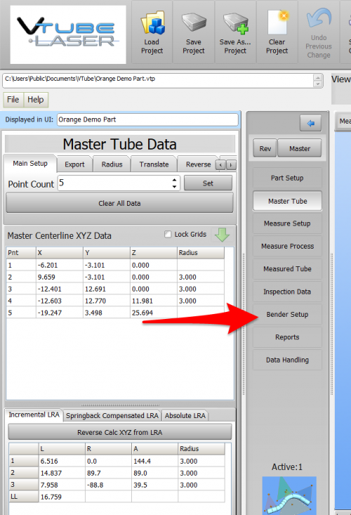
 How to SEND MASTER LRA Data to the UNISON Control from VTube-LASER
You can also send the new LRA data from the VTube-LASER BENDER SETUP menu to the UNISON bender using the VTube Bender Output menu.
|
Press the "BENDER SETUP button in the Navigation Pane. |
STEP 2 - Choose the BENDER NUMBER
|
Set the correct bender number at the top of the window. |
STEP 3 - Setup the Bender Setup Data in this WINDOW
|
This is for first-time setup for a new part. Data in this window is separate from data in the main VTube-LASER window, so it is necessary to bring data into this window when performing first-time setup of a part. This ensures that the correct data is sent to the UNISON.
|
STEP 3 - Send data to the UNISON BENDER
|
STEP 4 - The Send to Bender Complete Window
|
A window indicating that data was sent should appear for a few seconds then disappear automatically. |
STEP 5 - IMPORT the Data at the UNISON Control
|
In the YBC page, press the measuring center button. |
STEP 6 - READ NOMINAL
|
 How to SEND CORRECTION Data to the UNISON Control from VTube-LASER
STEP 1 - Bend the Tube
|
Bend the tube in the UNISON. |
STEP 2 - Measure the tube with VTube-LASER
|
Measure and align the tube to determine if it qualifies by falling within the envelope tolerance for the tube shape. |
STEP 3 - Enter BENDER SETUP
|
Click on the BENDER SETUP button in the Navigation Pane. |
|
For dual screen systems, VTube-LASER will let you press the Switch Screens button in the upper right corner in order to move the Bender Setup window to the second screen like this: |
STEP 4 - Choose the BENDER NUMBER
|
Set the correct bender number at the top of the window. |
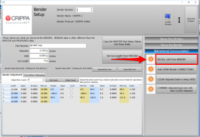
STEP 5 - RECALL CRIPPA YBC data
|
Be sure the that the Part Number value is the same as the part name in the CRIPPA control. The CRIPPA will not return data unless it recognizes the part number. |
STEP 6 - OPTIONAL STEP - You Can Manually Change the ADJUSTMENT Values
|
You can manually change the ADJUSTMENT values before sending corrections if you want to. Some users like to set the first and last Length adjustment to zero in order to keep the start position of the carriage in the same place - for when they have extra length on the ends. |
STEP 7 - Send the CORRECTION Values to the CRIPPA
|
Click on AUTO SEND. This will send the ORANGE columns to the CRIPPA bender.
|
STEP 8 - The SEND ADJUSTED Window
|
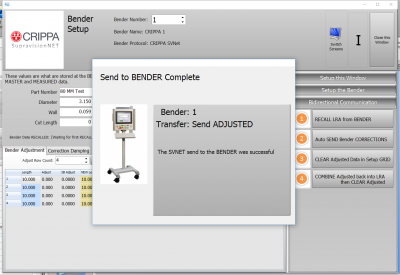
A window should appear for a few seconds indicating that the Send to the Bender is complete. |
STEP 9 - SAVE the New Data at the CRIPPA UII Software
|
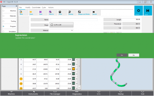
Move to the CRIPPA control. CRIPPA will ask for confirmation to update when it receives the incoming data. Say "Yes". |
STEP 10 - REPEAT STEPS 1 THROUGH 9
|
Bend the tube in the CRIPPA (Step 1) then measure it again (Step 2) and follow the rest of the steps until the part is within tolerance. |
Other Pages
- See VTube-LASER
- See VTube-STEP
- See CRIPPA for information on CRIPPA benders
