Difference between revisions of "VTube-LASER Cylinder Fit Tolerances"
(→The Cylinder Fit Data Window Reports How Well the Centerline Fits the Surface Data) |
(→How to Test for and Use Cylinder Fit Tolerances for Your Application) |
||
| (51 intermediate revisions by one user not shown) | |||
| Line 1: | Line 1: | ||
| − | |||
| − | |||
<table> | <table> | ||
<tr cellpadding=10> | <tr cellpadding=10> | ||
| − | <td width= | + | <td width=300> |
| − | + | How Does VTube-LASER Use Cylinder Fit Tolerances? | |
| − | + | ||
| + | |||
* Back to [[VTube-LASER]] | * Back to [[VTube-LASER]] | ||
* Back to [[VTube-STEP]] | * Back to [[VTube-STEP]] | ||
</td> | </td> | ||
<td width=300> | <td width=300> | ||
| − | [[image:vtube- | + | [[image:vtube-laser_logo_1.96.png|200px]]<br><br><br> |
</td> | </td> | ||
</tr> | </tr> | ||
| Line 17: | Line 16: | ||
<br> | <br> | ||
| − | + | __TOC__ | |
| − | = | + | =Answer= |
<table> | <table> | ||
<tr> | <tr> | ||
<td width=400> | <td width=400> | ||
| − | VTube-LASER uses surface points | + | VTube-LASER uses scanned surface points to calculate tube centerlines.<br><br> |
Regular tube scans assume that the primitive shape to solve for is a cylinder. But we also assume that no cylinder that we measure in the real world is a '''perfect''' cylinder.<br><br> | Regular tube scans assume that the primitive shape to solve for is a cylinder. But we also assume that no cylinder that we measure in the real world is a '''perfect''' cylinder.<br><br> | ||
VTube-LASER has to overcome this issue when measuring tube straights.<br><br> | VTube-LASER has to overcome this issue when measuring tube straights.<br><br> | ||
| Line 40: | Line 39: | ||
After calculating a cylinder centerline from surface points, VTube-LASER reports how well the centerline FITS the surface points of the cylinder. These values are shown in the Cylinder Fit Data window.<br><br> | After calculating a cylinder centerline from surface points, VTube-LASER reports how well the centerline FITS the surface points of the cylinder. These values are shown in the Cylinder Fit Data window.<br><br> | ||
The values reported are...<br><br> | The values reported are...<br><br> | ||
| − | * RADIUS: Estimate the | + | * RADIUS: Estimate the precision of half the diameter.<br><br> |
| − | * X or Y POSITION: Estimate the | + | * X or Y POSITION: Estimate the precision the X or Y positions of the end points of the cylinder.<br><br> |
| − | These estimate values are calculated using | + | These estimate values are calculated using statistics. The values are standard deviation x 2, which means that it gives a 95% assurance that the these values are the precision of the positions.<br> |
| + | [[image:Vtube-laser_cylinderfitwindow2.jpg|300px]]<br> | ||
</td> | </td> | ||
<td width=350 VALIGN="top"> | <td width=350 VALIGN="top"> | ||
| + | [[image:cylindricity graphic.png|500px]]<br><br> | ||
[[image:wobble illustration.png|500px]]<br> | [[image:wobble illustration.png|500px]]<br> | ||
| − | |||
</td> | </td> | ||
</tr> | </tr> | ||
</table> | </table> | ||
| − | =Wobble | + | =Cylinder Wobble - The highest of the X or Y values= |
<table cellpadding=10> | <table cellpadding=10> | ||
<tr valign=top> | <tr valign=top> | ||
<td width=400> | <td width=400> | ||
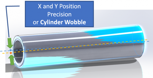
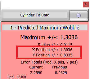
| − | To simplify visualizing the X and Y | + | To simplify visualizing the X and Y positions, we say that the '''highest of the X and Y values is the "cylinder wobble"'''. The cylinder wobble in the example on the right is 1.3036 inches - because it is the higher of the two values.<br><br> |
If the centerline calculation is very good, then wobble deviation decreases. If the calculation or fit is poor, then the wobble deviation is too high.<br><br> | If the centerline calculation is very good, then wobble deviation decreases. If the calculation or fit is poor, then the wobble deviation is too high.<br><br> | ||
| − | This Cylinder Fit Data window is | + | This Cylinder Fit Data window is Red because VTube-LASER found that the X and Y Position tolerances were exceeded in the cylinder centerline fit. In this case, VTube asked the operator to remeasure the straight because the cylinder wobble was too high as defined by the tolerances in System Options/Measure 1. |
<br> <br> | <br> <br> | ||
</td> | </td> | ||
<td width=350> | <td width=350> | ||
| − | [[image:vtube- | + | [[image:vtube-laser_wobbledeviation2.png|300px|right]] |
</td> | </td> | ||
</tr> | </tr> | ||
| Line 67: | Line 67: | ||
</table> | </table> | ||
| − | = | + | =Controlling Cylinder Fit Tolerance Values= |
| + | VTube-LASER uses tolerance values to decide when to warn you about potentially poor cylinder measurements.<br><br> | ||
| + | These values can be adjusted in the Measure 1 menu of System Options. | ||
| − | + | ==Default Tolerances== | |
| − | + | ||
| − | + | ||
| − | + | ||
| − | + | ||
| − | + | ||
| − | + | ||
| − | + | ||
| − | + | ||
| − | + | ||
| − | + | ||
| − | + | ||
| − | + | ||
| − | + | ||
| Line 89: | Line 78: | ||
<tr valign=top> | <tr valign=top> | ||
<td width=300> | <td width=300> | ||
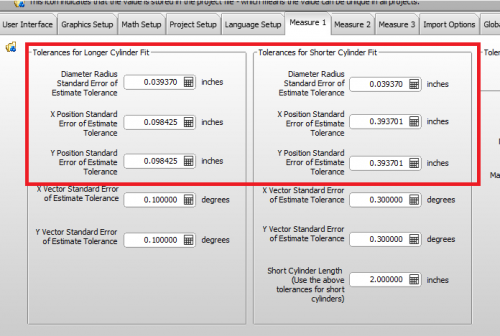
| − | + | The default values are designed as a good starting point in the VTube-LASER setup. They are excellent for quick demonstrations of the software, and work great for tubes that have a lot of deformation in the straights.<br><br> | |
| − | + | Large-diameter applications (like exhaust pipes) are good candidates for this setup.<br><br> | |
</td> | </td> | ||
<td width=500> | <td width=500> | ||
| − | [[image:vtube- | + | [[image:vtube-laser_default_CylinderFitTolerances2.png|500px|right]] |
</td> | </td> | ||
</tr> | </tr> | ||
| Line 99: | Line 88: | ||
</table> | </table> | ||
| − | + | ==Aerospace Tolerances== | |
| − | == | + | |
| Line 106: | Line 94: | ||
<tr valign=top> | <tr valign=top> | ||
<td width=300> | <td width=300> | ||
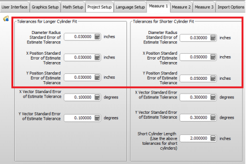
| − | + | Aerospace-grade materials are more precise compared to other applications. For aerospace applications, we recommend that you use tighter tolerances like the ones shown here.<br><br> | |
| − | + | The XY Positions are set to 0.030" for longer straights, and 0.050" for shorter straights. ("Short" is also definable with the variable in the lower right corner. It is set to 2" length by default.) | |
</td> | </td> | ||
<td width=500> | <td width=500> | ||
| − | [[image:vtube-laser_default_CylinderFitTolerances | + | [[image:vtube-laser_default_CylinderFitTolerances aerospace1.png|500px|right]] |
</td> | </td> | ||
</tr> | </tr> | ||
| Line 116: | Line 104: | ||
</table> | </table> | ||
| − | ==How to Test for | + | ==How to Test for and Use Cylinder Fit Tolerances for Your Application== |
| Line 127: | Line 115: | ||
Test for ideal cylinder fit tolerance settings by measuring tubes and watching the tolerance values in the Cylinder Fit window.<br><br>You will learn that your material regularly measures with certain maximum fit deviations.<br><br> | Test for ideal cylinder fit tolerance settings by measuring tubes and watching the tolerance values in the Cylinder Fit window.<br><br>You will learn that your material regularly measures with certain maximum fit deviations.<br><br> | ||
| − | As an example, if you never see deviations over 0. | + | As an example, if you never see deviations over 0.0159" (like shown on the right), you could set the tolerance value to 0.040" (which is just over double the max observed). If a cylinder fit deviation exceeds double the norm, then you can safely assume that there is a problem in the measurement, and you should be warned.<br><br> |
When watching for these values during measurements, keep in mind that you need to consider both the longer straight and shorter straight tolerances. Short straights will nearly always need higher tolerances. | When watching for these values during measurements, keep in mind that you need to consider both the longer straight and shorter straight tolerances. Short straights will nearly always need higher tolerances. | ||
| Line 133: | Line 121: | ||
To change the default values, be sure to CLEAR the VTube-LASER project first, then press the "Set Project Default State to the current state" button. This will use the new default cylinder fit tolerances for all new projects.</td> | To change the default values, be sure to CLEAR the VTube-LASER project first, then press the "Set Project Default State to the current state" button. This will use the new default cylinder fit tolerances for all new projects.</td> | ||
<td width=500> | <td width=500> | ||
| − | [[image:Vtube- | + | [[image:Vtube-laser_cylinderfitwindow3.jpg|300px]]<br><br> |
| − | [[image:vtube set default project state to the current | + | [[image:vtube set default project state to the current state1.png|400px]] |
</td> | </td> | ||
</tr> | </tr> | ||
| Line 140: | Line 128: | ||
</table> | </table> | ||
| − | ==Other Pages | + | =Why Are There Separate Values for Shorter Straights?= |
| + | |||
| + | |||
| + | <table cellpadding=10> | ||
| + | <tr valign=top> | ||
| + | <td width=300> | ||
| + | Math engines cannot calculate short straights as accurately as long straights. This has to do with the nature of cylinder math. It's a common issue with all measuring centers. Because of this, we know that VTube needs to be more patient with when fitting a cylinder centerline when the straight length is below a certain value.<br><br> | ||
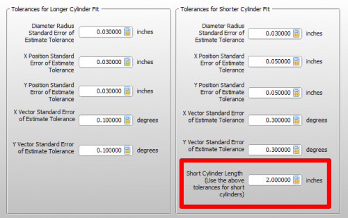
| + | In the default setup for VTube-LASER, a straight is considered "short" when it is 2 inches (50.8 millimeters) or shorter. | ||
| + | </td> | ||
| + | <td width=500> | ||
| + | [[image:vtube-laser_default_CylinderFitTolerances short straight value.png|500px|right]] | ||
| + | </td> | ||
| + | </tr> | ||
| + | |||
| + | </table> | ||
| + | |||
| + | =Other Pages= | ||
* Back to [[VTube-LASER]] | * Back to [[VTube-LASER]] | ||
| − | * | + | * See also [[Why VTube-LASER Reduces Data to Centerlines]] |
| + | * See also [[VTube-LASER Prioritizes Measuring Tube Straights]] | ||
Latest revision as of 13:55, 24 June 2022
|
How Does VTube-LASER Use Cylinder Fit Tolerances?
|
Contents |
Answer
|
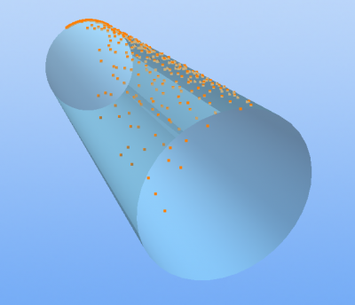
VTube-LASER uses scanned surface points to calculate tube centerlines. |
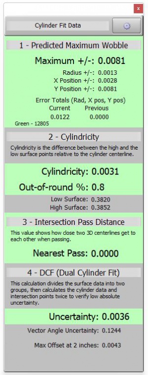
The Cylinder Fit Data Window Reports How Well the Centerline Fits the Surface Data
Cylinder Wobble - The highest of the X or Y values
|
To simplify visualizing the X and Y positions, we say that the highest of the X and Y values is the "cylinder wobble". The cylinder wobble in the example on the right is 1.3036 inches - because it is the higher of the two values. |
Controlling Cylinder Fit Tolerance Values
VTube-LASER uses tolerance values to decide when to warn you about potentially poor cylinder measurements.
These values can be adjusted in the Measure 1 menu of System Options.
Default Tolerances
|
The default values are designed as a good starting point in the VTube-LASER setup. They are excellent for quick demonstrations of the software, and work great for tubes that have a lot of deformation in the straights. |
Aerospace Tolerances
|
Aerospace-grade materials are more precise compared to other applications. For aerospace applications, we recommend that you use tighter tolerances like the ones shown here. |
How to Test for and Use Cylinder Fit Tolerances for Your Application
|
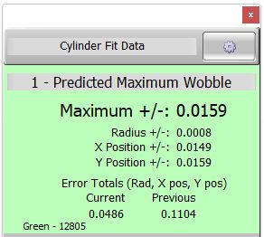
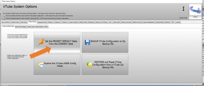
You can adjust the tolerances in System Options to better fit your application and increase the assurance that your centerline is a good fit to the surface data. Test for ideal cylinder fit tolerance settings by measuring tubes and watching the tolerance values in the Cylinder Fit window. As an example, if you never see deviations over 0.0159" (like shown on the right), you could set the tolerance value to 0.040" (which is just over double the max observed). If a cylinder fit deviation exceeds double the norm, then you can safely assume that there is a problem in the measurement, and you should be warned. When watching for these values during measurements, keep in mind that you need to consider both the longer straight and shorter straight tolerances. Short straights will nearly always need higher tolerances. To change the default values, be sure to CLEAR the VTube-LASER project first, then press the "Set Project Default State to the current state" button. This will use the new default cylinder fit tolerances for all new projects. |
Why Are There Separate Values for Shorter Straights?
|
Math engines cannot calculate short straights as accurately as long straights. This has to do with the nature of cylinder math. It's a common issue with all measuring centers. Because of this, we know that VTube needs to be more patient with when fitting a cylinder centerline when the straight length is below a certain value. |
Other Pages
- Back to VTube-LASER
- See also Why VTube-LASER Reduces Data to Centerlines
- See also VTube-LASER Prioritizes Measuring Tube Straights
