Difference between revisions of "Benderlink Ethernet Module for PINES to Vector"
From ATTWiki
(→About the Connections) |
(→Inside the Module) |
||
| Line 32: | Line 32: | ||
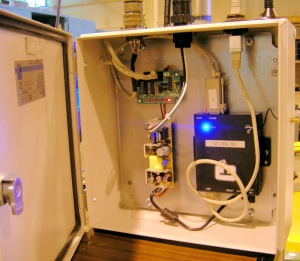
*The Ethernet Serial Device Server is the black box on the right.<br><br> | *The Ethernet Serial Device Server is the black box on the right.<br><br> | ||
*The power supply is on the lower left.<br><br> | *The power supply is on the lower left.<br><br> | ||
| − | | [[image: | + | | [[image:Blink_module_vector_test3.jpg|300px]] |
|} | |} | ||
Revision as of 13:16, 2 May 2008
About the Connections
Inside the Module
Example Installation
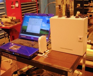
This is an image of the box installed on a test bench computer running Benderlink for Eaton Leonard, which simulates Vector 1 Laservision communications.

Purchasing
This item can be purchased from our Online Store
Other Pages
- Benderlink Current Loop Module page
- Benderlink page
- Read more about the current loop board here: Communications Board for Eaton Leonard - CB-EL1

