Difference between revisions of "VTube Communication for SOCO"
(→Setup the Benderlink for the SOCO Bender) |
(→Setup the Benderlink for the SOCO Bender) |
||
| Line 66: | Line 66: | ||
<tr valign=top> | <tr valign=top> | ||
<td width=500> | <td width=500> | ||
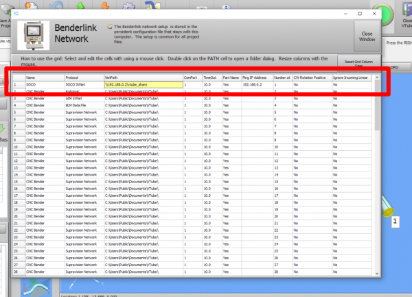
| − | #Choose an unused row in the grid for a new SOCO bender setup.<br><br> | + | #Choose an unused row in the grid for a new SOCO bender setup. (Click on the image at the right to see a zoomed image.)<br><br> |
#Assign a bender name that will help operators identify what this bender is. This text will be displayed at the top of the Bender Setup menu.<br><br> | #Assign a bender name that will help operators identify what this bender is. This text will be displayed at the top of the Bender Setup menu.<br><br> | ||
#Assign the SOCO SVNet protocol.<br><br> | #Assign the SOCO SVNet protocol.<br><br> | ||
Revision as of 19:33, 9 September 2016
|
VTube-STEP and VTube-LASER Communications with SOCO Benders |
Protocol
|
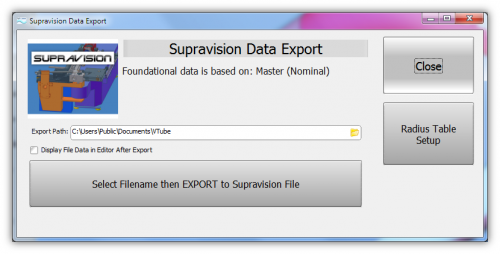
VTube-STEP can export Supravision data to SOCO benders using the SOCO SVNet protocol. |
Communications Setup with the SOCO Bender
|
Setup Benderlink inside of VTube-STEP or VTube-LASER
Entering Benderlink Setup
|
Setup the Benderlink for the SOCO Bender
|
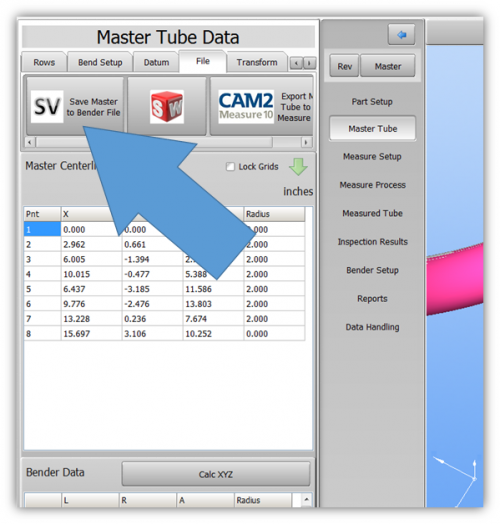
How to SEND MASTER XYZ Data to the SOCO Control
|
You can import data into VTube-LASER |
Using VTube-LASER to send NEW MASTER Data to YLM Benders
|
The connection the bender is made with standard network connection, and a shared folder location between the VTube computer and the operator station computer. For a NEW TUBE, the YLM takes in VTube MASTER Supravision LRA data in a Supravision file.
|
Follow these steps at VTube-LASER to Send a NEW TUBE SETUP to a YLM Bender
|
STEP 1 |
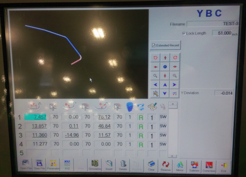
Follow these steps at the YLM CONTROL to import the MASTER data from VTube-LASER
STEP 1
|
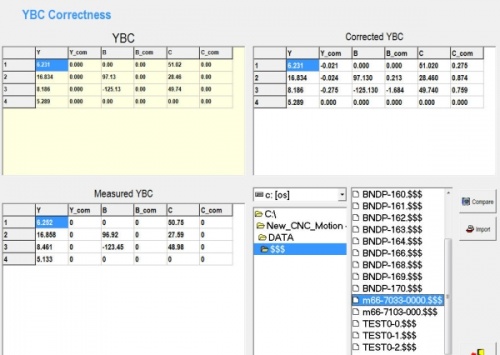
In the YLM control, clear the YBC data. (Note:Clearing is optional. It is not always necessary - but seems to keep data from overlapping between older and newer setups.) |
STEP 2
|
|
STEP 3
|
In the lower right corner of the screen, select the drive and path then explore for and select the $$$ file that was created by VTube-LASER. |
STEP 4
|
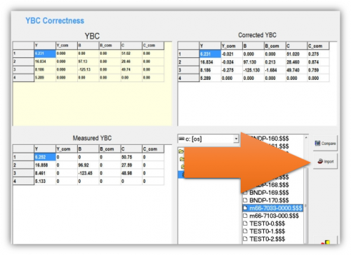
In the YLM YBC menu, click on IMPORT. (Do not click "COMPARE" - as that is for corrections.) |
STEP 5
|
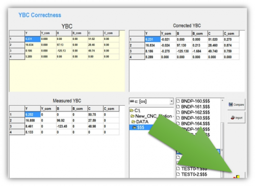
Press the Exit menu close button in the lower right corner of the screen. |
STEP 6
|
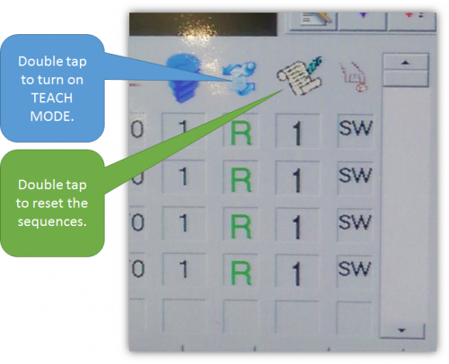
In order to exit the YBC screen, you might need to double tap on the teach mode button in order to turn on teach mode. Then double tap on the sequences icon on the top of the sequences column. Reset the sequences. |
VTube-LASER CORRECTION Steps for YLM Benders
|
The connection the bender is made with standard network connection, and a shared folder location between the VTube computer and the operator station computer.
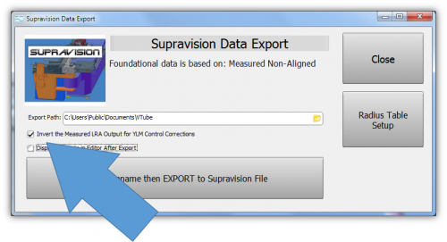
Handling Opposite CorrectionsThere are two ways to overcome the opposite correction problem: 1 - Use a special INVERSION checkbox in the VTube Supravision Export menu. Only use this inversion switch when sending measured data for correction. 2 - Have the YLM technician change the internal low level setting in the YLM control that makes the correction be apply in the normal way. |
Follow these steps at VTube-LASER to Correct a YLM Bender
STEP 1
|
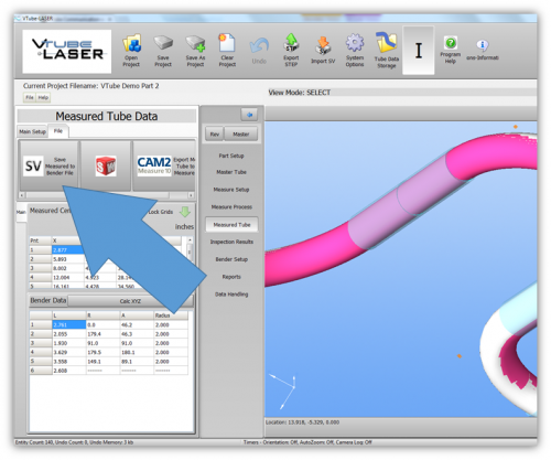
Switch to the MEASURED TUBE window and press the FILE tab. |
STEP 2
|
Most YLM benders use the pure MEASURED data for corrections. However, some YLM benders need the MEASURED data changed into the CORRECTED data - and the CORRECTIONS are always made based on the MASTER data (not the existing data in the bender). We call this "YBC Correction Inversion". |
STEP 3
|
Save the Supravision file. |
STEP 4
|
Move to the YLM control and follow the steps below to import the correction. |
Follow these steps at the YLM CONTROL to import the measured data from VTube-LASER
STEP 1
|
In the YLM YBC menu, click on CORRECTION. |
STEP 2
|
Search for and select the $$$ file that was created by VTube-LASER. |
STEP 3
|
Select COMPARE to bring the data into the YLM control. The COMPARE button will only display when a file is selected.
|
STEP 4
|
Press the menu close button in the lower right corner. |
Shutdown to Edit the Windows Setup
To shutdown the YLM software to configure Windows settings:
- Press the Shutdown button.
- Press "NO" for shutdown.
- Type "12345" and OK in the numeric keypad.
- YLM will close without shutting down the computer.
Other Pages
- See VTube-LASER
- See VTube-STEP
- See YLM for information on the YLM benders


