Difference between revisions of "VTube Communication with AMOB"

From ATTWiki
Jump to: navigation, search
(Created page with "==About this Page== <table width=1000> <tr valign=top> <td width=300> This page describes the setup and use of the VTube to AMOB communications.<br><br> </td> <td width=500> [...")

Revision as of 18:15, 7 October 2016

About this Page

This page describes the setup and use of the VTube to AMOB communications.

SOCO Logo with Bender.png


Tested and Verified Communications

The developers from SOCO, TFS, and Advanced Tubular have thoroughly tested the features explained in this page.

If you have any questions, please contact Michael Cone at Advanced Tubular Technologies, or Kyle Eagle at TFS (Tube Form Solutions - Distributor for SOCO).

See Video 62 - SOCO Communications Video to see an actual corrections loop with a SOCO bender.
Protocol

VTube-STEP can export Supravision data to SOCO benders using the SOCO SVNet protocol.

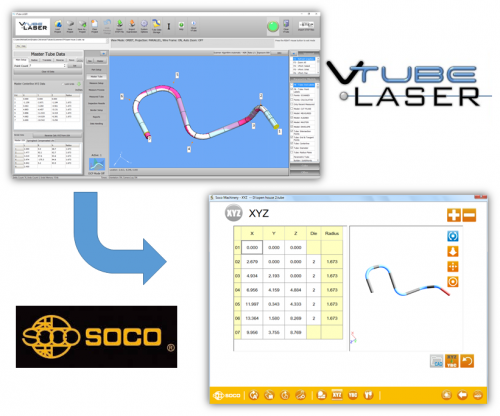
VTube-LASER, the version of VTube that connects to a FARO measuring center arm, can send measured data to the SOCO control for corrections.

Faro scanner v6.png

VTube-LASER to Soco XYZ.png

Communications Setup at the SOCO Bender

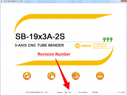
  • Correct communications requires at least Revision 728 (September 10, 2016) of the SOCO software. (The control filenames include the revision number in the name like this: "NVS728.exe". The executable file is in the "c:\Program Files (x86)\Bending Machine" folder. You can see the SOCO NVC revision number also at the bottom of the startup screen (See the right image.)

  • Connect the SOCO bender to the network using a standard Ethernet cable. SOCO computers can be accessed through the lower front of the operator station. Run the cable through the small side door on the right, and up to the computer system. The SOCO control computer will have Ethernet ports available for connection.

  • Setup a shared network location either in the SOCO windows control or in a network path on your network.

  • In the SOCO YBC screen, press the measuring center button.

  • Enter the shared network path in the Exchange Directory field. This path name cannot be a UNC name (like \\192.168.0.2\VTube\). It must be a path with a drive and a path that follows. If you must network to a location on the network, then map a drive letter to that location, and use the mapped drive letter in this field.

  • Enter the bender number. Each bender number needs to have a unique number in the network. The bender number must be 1 or higher. Don't use "0" for the bender number, because VTube requires a bender number that is at least 1.

  • Activate the SV/SV Network communications. Touch the checkbox field until it shows a check mark (see the image on the right).

Soco Startup Screen.png

Soco Measuring Center Setup.png

Setup Benderlink at VTube-STEP or VTube-LASER

Entering Benderlink Setup

  1. Enter the VTube System Options menu.

  2. Enter the Measure 2 tab menu.

  3. Enter the Setup Benderlink Network menu.

VTube System Options Benderlink Network Button.png

Setup the Benderlink Network Grid for the SOCO Bender

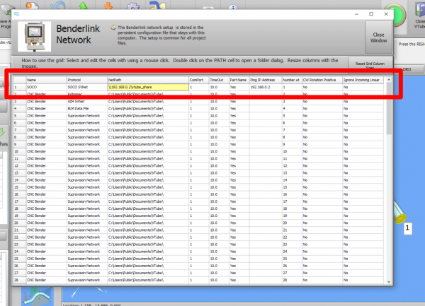
  1. Choose an unused row in the grid for a new SOCO bender setup. (Click on the image at the right to see a zoomed image.)

  2. Assign a bender name that will help operators identify what this bender is. This text will be displayed at the top of the Bender Setup menu.

  3. Assign the SOCO SVNet protocol.

  4. Enter the path to the shared drive or folder in the NetPath field. Use the same location as the SOCO setup. VTube accepts UNC names as well as regular paths with drive letters.

  5. Enter the IP address in the PING IP ADDRESS field if it is a fixed field. (This is not required. It allows VTube to ping the address to see if the network location is active before trying to open communications.)

  6. Press Close to save the settings. VTube will save these values to a persistent configuration file that will not change unless you change them in this grid.

VTube Benderlink Setup for SOCO SVNet.png

How to SEND MASTER XYZ Data to the SOCO Control from VTube-STEP

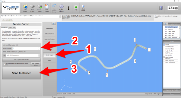
You can import data into VTube-STEP then send the XYZ Centerline data calculated to the SOCO bender using the VTube Bender Output menu.

At the SOCO Control

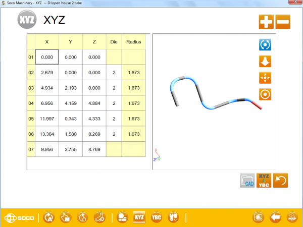
At the SOCO control, enter the SOCO XYZ Screen. With the XYZ Screen open, the SOCO control will understand that it must extract the MASTER XYZ data in the incoming data and import that into the SOCO NVS software.

SocoXYZscreen.png


At the VTube-STEP Computer

Move to the VTube-STEP computer and follow these steps to transfer the XYZ data to the SOCO.

  1. Press the Bender Output button in the navigation pane.
  2. Set the correct bender number.
  3. Press the Send to Bender button.


The SOCO will receive new data and ask if it should be imported with a dialog. Press YES to import the data.

VTube-STEP Bender Output to SOCO.png


How to SEND MASTER XYZ Data to the SOCO Control from VTube-LASER

You can also send the new XYZ Centerline data from the VTube-LASER BENDER SETUP menu to the SOCO bender using the VTube Bender Output menu.

Enter the XYZ Screen At the SOCO Control

At the SOCO control, enter the XYZ Screen. With the XYZ Screen open, the SOCO control will understand that it must extract the MASTER XYZ data in the incoming data and import that into the SOCO NVS software.

SocoXYZscreen.png

Enter the BENDER SETUP menu in VTube-LASER

Follow these steps in the VTube-LASER:

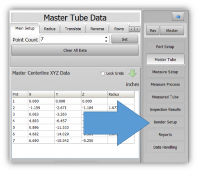
Press the "BENDER SETUP button in the Navigation Pane.

Vtube-laser 2.7 bendersetup button navigationpane.png

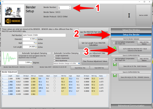
STEP 1 - Set the correct bender number at the top of the window. As of version 2.7, the SOCO SVNet option is available - which means you should see a SOCO bender at the top left corner of the screen.


STEP 2 - On the right click on "Setup the Bender".


STEP 3 - Click on AUTO SEND

The SOCO will receive new data and ask if it should be imported with a dialog. Press YES to import the data.

Vtube-laser v2.7 send master to soco.png


How to SEND CORRECTION Data to the SOCO Control from VTube-LASER

At the SOCO Control

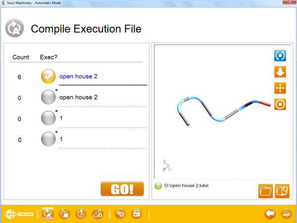
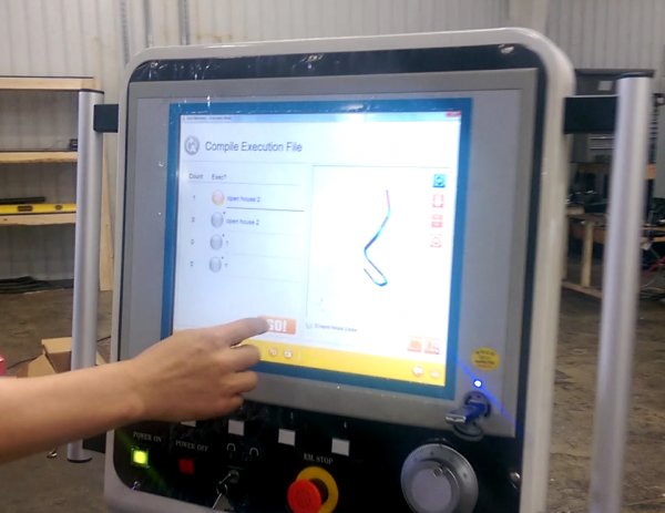
At the SOCO control, setup and bend the first tube through the YBC and then Compile Execution screen.

Soco compile execution screen.png

After Bending the Tube

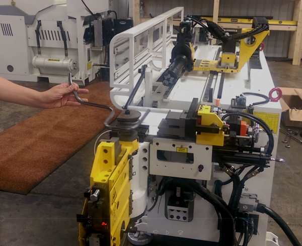
After the bending cycle is complete, remove the tube from the dies. Leave the bender in AUTO mode.

Soco remove part from bender.png


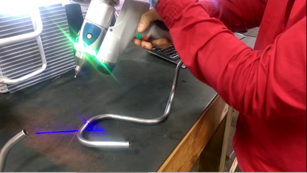
Measure the tube with VTube-LASER

Measure and align the tube to determine if it qualifies by falling within the envelope tolerance for the tube shape.

In the VTube-LASER screen shot, you see the actual result of the first tube not qualifying in shape. The red cells in the tangent point grid on the lower left show that the measured tube centerline is out-of-tolerance.

Vtube-laser v2.7 soco part measure.png

Vtube-laser v2.7 soco out of tolerance.png


Correct the SOCO with VTube-LASER - Enter BENDER SETUP

Follow these steps in the VTube-LASER:

Press the "BENDER SETUP button in the Navigation Pane.

Vtube-laser 2.7 bendersetup button navigationpane.png

RECALL SOCO YBC data and then SEND CORRECTIONS

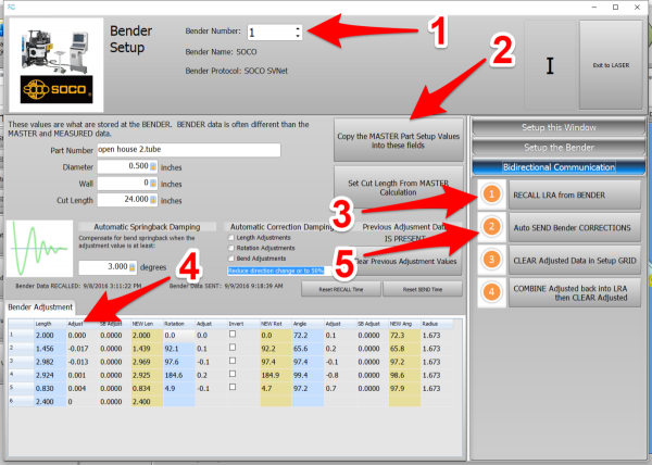
STEP 1 - Set the correct bender number at the top of the window. As of version 2.7, the SOCO SVNet option is available - which means you should see a SOCO bender at the top left corner of the screen.


STEP 2 - If the Part Number is empty, then press the Copy the Master Part Setup values.


STEP 3 - Click on RECALL. This will update the BLUE columns in the Bender Setup.


STEP 4 - You can manually change the ADJUSTMENT values before sending corrections. In this case, we set the first and last Length adjustment to zero in order to keep the start position of the carriage in the same place.


STEP 5 - Click on AUTO SEND. This will send the ORANGE columns to the SOCO bender.

Vtube-laser v2.7 soco send correction.png


At the SOCO Bender - Press GO!

Press GO! The SOCO will compile the changes.

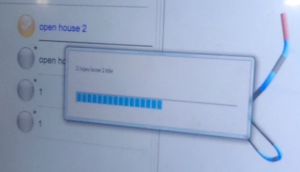
You will see a progress bar after you press GO!

Soco press go compile execution progressbar.png

Soco press go compile execution.png

The "Auto Compensation Completed" message will appear in the lower right corner.

Bend the corrected part now.

Soco auto compensation completed.png

Measure at the VTube-LASER Computer

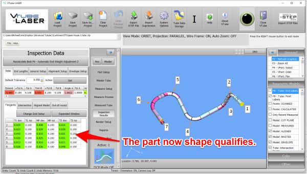
Measure and align the tube again to determine if it qualifies by falling within the envelope tolerance for the tube shape.

This screen shot shows an actual resulting change after the correction.

Vtube-laser v2.7 soco part qualifies.png


Other Pages