Difference between revisions of "VTube Communication for BLM VGP3D"
(→Initialize the New Values in the VGP-3D Software at the BLM) |
(→AMOB Control Bender Data Updated) |
||
| Line 252: | Line 252: | ||
</table> | </table> | ||
| − | === | + | ===Send the Program to the Bender and Bend the Part=== |
<table cellpadding=10> | <table cellpadding=10> | ||
<tr valign=top> | <tr valign=top> | ||
| Line 258: | Line 258: | ||
| − | + | * Send the new data to the bender.<br><br> | |
| − | Bend the corrected part. | + | * In the BLM, you can run the simulator with the new data.<br><br> |
| + | * Bend the corrected part. | ||
| + | * Take it back to VTube-LASER to measure again. | ||
</td> | </td> | ||
Revision as of 21:51, 23 June 2017
About this Page
|
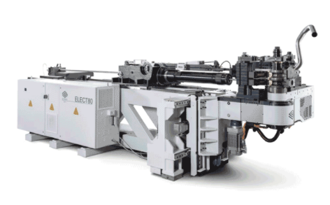
This page describes the setup and use of the VTube to BLM communications. |
The Basics of How It Works
|
Communications Setup at the BLM Bender
|
Setup Benderlink at VTube-STEP or VTube-LASER
Entering Benderlink Setup
|
Setup the Benderlink Network Grid for the BLM Bender
|
How to SEND CORRECTION Data to the BLM Control from VTube-LASER
After Bending the Tube
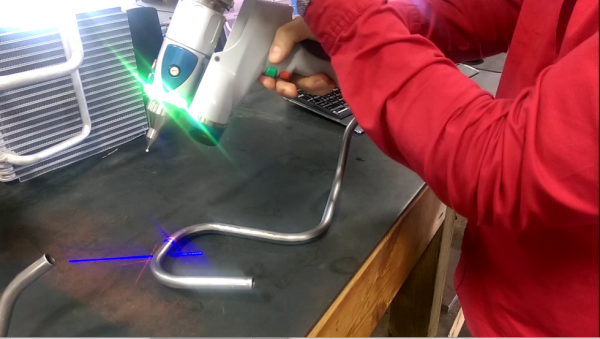
Bend a tube then measure it with VTube-LASER.
Measure the tube with VTube-LASERMeasure and align the tube to determine if it qualifies by falling within the envelope tolerance for the tube shape.
|
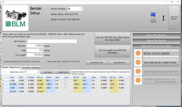
Correct the BLM with VTube-LASER - Enter BENDER SETUP
|
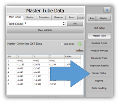
Follow these steps in the VTube-LASER: Press the "BENDER SETUP button in the Navigation Pane. |
INITIAL RECALL Setup of Bender Setup Window
|
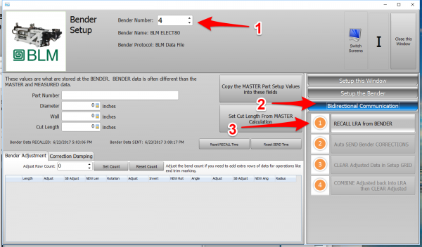
The first time in this window for a new part will require these steps before you can correct the BLM bender. These steps assume that you have programmed a part in the bender, and that you have measured and aligned a part. STEP 1 - Set the correct bender number at the top of the window. The BLM bender should display if you have already setup the bender protocol in the Benderlink grid.
|
RECALL Warning Boxes
|
VTube-LASER will probably warn you that the incoming data count and part number does not match what is in VTube-LASER.
|
AFTER RECALL
|
After the RECALL, the Blue Columns will show the data that is programmed in the BLM control. |
Send the Corrections to the BLM File
|
|
Dialogs Inside the Send Corrections Feature
|
STEP 1 - The first dialog explains how communications happens - but file merge. |
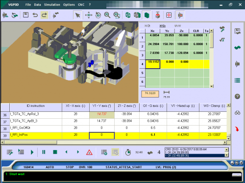
Load the New BLM File Into the VGP-3D Software at the BLM
|
Load the BLM data VTube just saved into the VGP-3D software. |
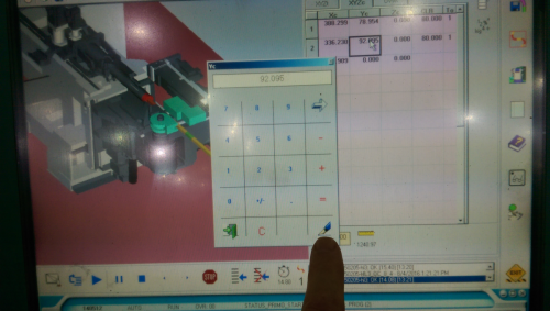
CRITICAL STEP: Initialize the New Values in the VGP-3D Software at the BLM
|
This next step is CRITICAL for proper operation of the BLM software. Without it, the new data will not be sent to the PLC.
This will initialize the data in the rest of the BLM program. |
Send the Program to the Bender and Bend the Part
|
|
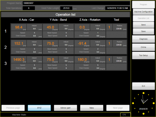
Synchronizing the VTube-LASER and AMOB Data Before Corrections
|
It is critical to be sure the blue columns contain the same data that the AMOB X Axis, Y Axis, Z axis values have before correction is applied. To make the data the value the same for the next correction, you can press the bottom button in the Bidirectional Communications menu on the right. Be sure you do this BEFORE you measure the next corrected part. The reason for this step is because the AMOB does not allow VTube to RECALL data in order to update the BLUE columns for the next correction. So this process must be performed manually. The data in the blue and the orange columns will now be identical. You can exit this window and measure the next corrected part. |
Other Pages
- See VTube-LASER
- See VTube-STEP

