|
VTube-LASER uses the legacy Eaton Leonard Current Loop protocol to communicate with Premier controls. The protocol requires that an RS-232 signal be converted to Current Loop, then sent to the bender.
This diagram demonstrates how a Benderlink Ethernet Module completes the Current Loop connection between a FARO VTube-LASER computer to an Eaton Leonard Premier, or EL-2000 bender control.
The Benderlink Ethernet Module can be wired or WiFi wireless (optional).
|

|
HOW TO SWITCH COMMUNICATIONS ON AT THE PREMIER CONTROL
Communications between VTube-LASER and the Premier is very easy to do because it's robust and also very intuitive.
|
All communications from the PREMIER control occurs in the VECTOR 1 screen shown here.
VTube-LASER knows how to communicate using the VECTOR 1 protocol.
When you enter this screen note that the REQUEST TRANSFER box on the right is BLACK. This means that the Premier is not ready for communications yet.
|

|
Premier Communications Active
|
To put the Premier in communications mode, make the REQUEST TRANSFER box active (green) like is shown here. The WAITING field will be highlighted.
Before you make that button active, check on the following settings:
CHECK 1 - CORRECT MODE IS ACTIVE
The MODE in the upper left corner should read "EXTERNAL MODE". It is controlled by the yellow button on the bottom right side of the screen. This mode allows VTube-LASER to control the communications.
CHECK 2 - BENDER NUMBER MATCHES
The bender number in both this menu and the VTube-LASER Benderlink setup must agree. If they don't, then VTube and the PREMIER will at least issue warnings or dialogs.
|

|
HOW TO SEND NEW PART DATA FROM VTUBE-LASER TO THE PREMIER CONTROL
|
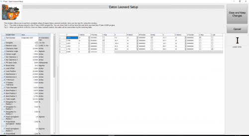
VTube-LASER (v2.7 or higher) will allow for the complete setup of all bender and setup data that can be stored in a Premier, EL2000, or Velog control in the Eaton Leonard Setup window.
Click on the image on the right to see a closeup of the Eaton Leonard Setup window.
You enter this window to setup the bender parameters.
|

|
How to Send a NEW Part
- Enter the Bender Setup window. Set the bender number (at the top of the window). The protocol should show Eaton Leonard. The bender image show show an Eaton Leonard bender.
- If the blue columns only have zeros, or there are no rows in the LRA grid, bring new part data into the Bender Setup window by using the Setup this Window button on the right. Click on "Copy MASTER LRA to Setup LRA". This will bring the MASTER LRA data from VTube-LASER's main memory into this Bender Setup screen.
- Press the Additional Bender Setup button at the top of the Bender Setup screen to load the Eaton Leonard Setup window.
- Edit any of the Eaton Leonard Setup values.
- Press the Close and Keep Changes button in the Eaton Leonard Setup window.
- In the Setup the Bender expanding menu on the right, press AUTO SEND. (Be sure that the bender is ready for communication. See the "Premier VECTOR 1 Menu With Communications Active" section above.)
|


|
Other Pages


