

|
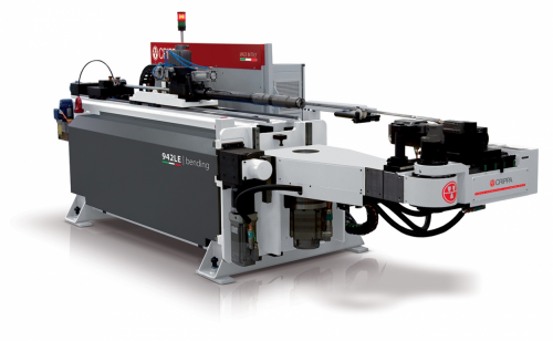
This page describes the setup and use of the VTube to CRIPPA Supravision file communications for newer CRIPPA benders that have the SVNET protocol. Descriptions for VTube-STEP and VTube-LASER is included.
Some of these steps require technical assistance from a CRIPPA or Advanced Tubular Technologies technician to complete the connection.
|
|
Protocol
|
VTube-STEP can send data directly to the CRIPPA UII software YBC values.
VTube-LASER can correct data in CRIPPA UII for YBC bender corrections.
|

|
Plug in Cable 2 In The CRIPPA HMI Computer
- Connect the CRIPPA bender to the network following the CRIPPA tech support instructions.
- Be sure that ethernet cable 2 is plugged into Ethernet port 2 on the CRIPPA HMI computer. The cable is stored initially under the keyboard shelf. You will need to drop the bottom of the shelf and uncoil the cable through the back like shown on the right.
- Plug in cable 2 to port 2, then cable tie the cable to the other cables so that it will not bind when the door closes.
- Be careful to NOT unplug or replace cable 1. This cable allows the CRIPPA software to communicate with the PLC inside the bender.
|


|
Plug The Other End of the Cable Into A Network Switch
- Find cable 2 inside the electrical cabinet on the back of the bender. This is the other end of the same cable you plugged into the CRIPPA HMI computer in the previous step.
- Plug this end of the cable into a network switch.
- Plug another cable from the network switch into the VTube computer.
|

|
Allow a Technician to Configure the CRIPPA and the VTube Computers
 These steps require technician-level assistance from CRIPPA or Advanced Tubular Technologies.
|
The technician will...
- Setup the IP address inside the CRIPPA HMI computer and inside the VTube computer
- Setup Supravision network communications.
- Share a CRIPPA folder and setup permissions for the VTube computer to read and write data to that folder.
|
|
Enable Supravision Communications in the CRIPPA UII Interface
|
The technician will...
- Setup the IP address inside the CRIPPA HMI computer and inside the VTube computer
- Setup Supravision network communications.
- Share a CRIPPA folder and setup permissions for the VTube computer to read and write data to that folder.
|
|
Test the Network Connection on the VTube Computer
 These steps require technician-level assistance from CRIPPA or Advanced Tubular Technologies.
|
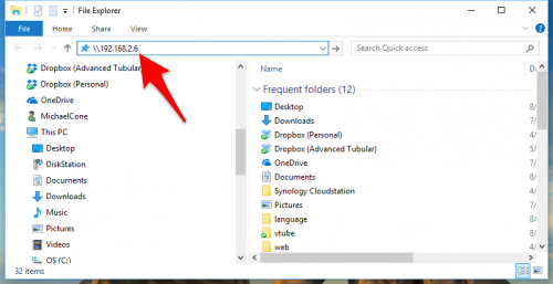
Test the network connection at the VTube computer using the Windows File Explorer.
- Open the File Explorer.
- Type in the network path for the CRIPPA computer. It is safest to use a fixed IP in the path like this: \\192.168.2.6
(The 192.168.2.6 is an example IP address. The number you will use will most likely be different.)
- Press Enter and allow the VTube to connect to the CRIPPA computer. This may take a few seconds.
- The CRIPPA computer will ask you to supply credentials (username and password).
- Enter the credentials supplied by the CRIPPA or Advanced Tubular technician, then be sure the check the "Remember my credentials" checkbox before pressing OK.
- If the connection works, then you will see a couple of folders in the File Explorer screen. One of them will be something like "SVTransfer". Double click on that folder. The path that you see in the top of the Explorer window is the path you will need to program into VTube for communications to the CRIPPA. So, for this example, the path to use in setting up VTube is "\\192.168.2.6\SVTransfer".
- Attempt to create a new text file in this folder. If you can, then the network connection is complete. VTube must be able to write files to this folder.
|


|
Setup Benderlink in VTube-STEP or VTube-LASER
Entering Benderlink Setup in VTube-STEP
|
You can perform this setup from VTube-STEP or VTube-LASER. The steps are identical in both.
- Load VTube.
- Enter the System Options menu.
- Enter the Measure 2 tab menu.
- Enter the Setup Benderlink Network menu.
|

|
Setup the Benderlink Network Grid for the CRIPPA Supravision Network
- Choose an unused row in the grid for a new CRIPPA bender setup. (Click on the image at the right to see a zoomed image.)
- Assign a bender name that will help operators identify which bender this is. This text will be displayed at the top of the Bender Setup menu.
- Assign the CRIPPA SVNet protocol.
- Enter the path to the shared drive or folder in the NetPath field. This path should point to the CRIPPA folder that will receive command files from VTube. (The value shown on the screen is only an example.)
- Enter the IP address in the PING IP ADDRESS field if it is a fixed field. (This is not required. It allows VTube to ping the address to see if the network location is active before trying to open communications.)
- If the Crippa rotates the Clockwise positive, then select YES in the CW Rotation Positive cell.
- The "Ignore Incoming Linear Unit" setting is optional. This will not allow the CRIPPA to change the linear units in VTube-LASER if they are different.
- Press Close to save the settings. VTube will save these values to a persistent configuration file that will not change unless you change them in this grid.
|

|
How to SEND MASTER XYZ Data to the CRIPPA Control from VTube-STEP
You can import data or models into VTube-STEP then send the calculated LRA bender data to the CRIPPA bender using the VTube BENDER OUTPUT menu.
|
In the BENDER OUTPUT menu.
- Select the bender number.
- Click on "Send to Bender"
|


|
STEP 2 - SAVE the Data at the CRIPPA UII Software
|
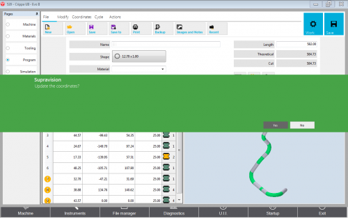
CRIPPA will ask for confirmation to update when it receives the incoming data. Say "Yes".
The YBC data will change to match the data that was sent from VTube. You can compare a few values to be sure the data was updated properly.
|
|
STEP 3 - SAVE and COMPILE
- Save and Compile, then Save the CRIPPA data again. (The UII program will ask you to save the data twice.)
- Run the simulation (if you want to).
- Setup and bend the part.
|

|
STEP 5 - LOAD the MPF File at the CRIPPA Control
|
At the CRIPPA control, open the new MPF file. |

|
How to SEND MASTER LRA Data to the CRIPPA Control from VTube-LASER
You can also send the new LRA data from the VTube-LASER BENDER SETUP menu to the CRIPPA bender using the VTube Bender Output menu.
|
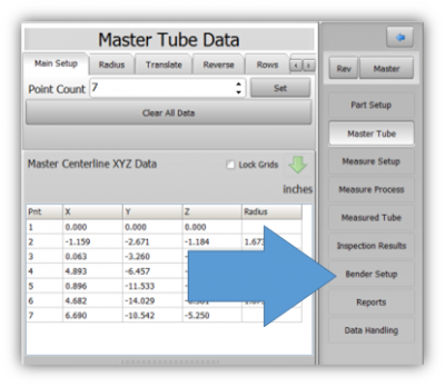
Press the "BENDER SETUP button in the Navigation Pane.
|
|
STEP 2 - Choose the BENDER NUMBER
|
Set the correct bender number at the top of the window.
You can select up to 100 different benders.
You should see a CRIPPA bender at the top left corner of the screen. The Bender Protocol should say "CRIPPA MPF Data File". (This assumes that you have already configured VTube's Benderlink in the Systems Options as described in the previous VTube-STEP section.)
|

|
STEP 3 - Setup the Bender Setup Data in this WINDOW
|
This is for first-time setup for a new part. This ensures that the correct data is sent to the CRIPPA. Data in this window is separate from data in the main VTube-LASER window, so it is necessary to bring data into this window when performing first-time setup of a part.
- Click on "Setup this Window" in the expanding menu on the right.
- Click on copy MASTER LRA to SETUP LRA.
- Be sure every field in the top panel has data that you want to send to the CRIPPA. The MPF file will contain everything in that panel except for the WALL THICKNESS.
- The blue columns below will eventually be converted to new YBC data at the bender. So check for numbers there.
- The radius column should contain the correct bend radii. This column will also be sent to the CRIPPA.
|

|
STEP 3 - Send data to the CRIPPA BENDER
|
This step will send new YBC data to a CRIPPA MPF File.
- Click on "AUTO SEND the MASTER XYZ + BLUE Columns to the Bender".
Note: For this protocol, the XYZ data is not sent. The CRIPPA file only contains LRA data converted to YBC data.
|

|
STEP 4 - The SEND SUCCESS Window Should Appear
|
A timed "SUCCESS" window should appear for a few seconds.
|

|
STEP 5 - LOAD the new MPF File at the CRIPPA Control
|
At the CRIPPA control, open the new MPF file. |

|
How to SEND CORRECTION Data to the CRIPPA Control from VTube-LASER
STEP 1 - Bend the Tube
|
Bend the tube in the CRIPPA.
|

|
STEP 2 - Measure the tube with VTube-LASER
|
Measure and align the tube to determine if it qualifies by falling within the envelope tolerance for the tube shape.
In the VTube-LASER screen shot, you see the actual result of the first tube not qualifying in shape. The red cells in the tangent point grid on the lower left show that the measured tube centerline is out-of-tolerance.
|

|
STEP 3 - Enter BENDER SETUP
|
Press the "BENDER SETUP button in the Navigation Pane.
|

|
STEP 4 - Choose the BENDER NUMBER
|
Set the correct bender number at the top of the window.
You can select up to 100 different benders.
You should see a CRIPPA bender at the top left corner of the screen. The Bender Protocol should say "CRIPPA MPF Data File". (This assumes that you have already configured VTube's Benderlink in the Systems Options as described in the previous VTube-STEP section.)
|

|
STEP 5 - RECALL CRIPPA YBC data
|
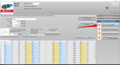
In the Bidirectional Communication menu on the right, click on RECALL.
This is a critical step during correction. If a RECALL is not performed before a CORRECTION, then VTube may not be able to properly sort out what is the NOMINAL data and what is the ADJUSTED in the MPF file. Be sure to perform this step before performing the CORRECTION step below.
|
|
STEP 6 - LOAD the CRIPPA File Data
|
In the Open File dialog, select the MPF file that you intend to correct and press Open.
This will update the BLUE columns in the Bender Setup, and also update the internal CRIPPA MPF data object that keeps the NOMINAL and ADJUSTED values separate from each other in the YBC data.
|

|
STEP 7 - Manually Setup the ADJUSTMENT Values
|
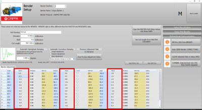
You can manually change the ADJUSTMENT values before sending corrections. Some customers like to set the first and last Length adjustment to zero in order to keep the start position of the carriage in the same place - for when they have extra length on the ends.
|
|
STEP 8 - Send the CORRECTION Values to the CRIPPA MPF File
|
Click on AUTO SEND. This will send the ORANGE columns to the CRIPPA bender.
To be sure that a RECALL has recently been performed, VTube will show a CRIPPA CORRECTIONS NOTES as a reminder.
The dialog also explains what happens next.
|

|
STEP 9 - Choose a CRIPPA MPF File to CORRECT
|
Choose the CRIPPA file that you want to correct.
Press the SAVE button.
|

|
STEP 10 - The SEND SUCCESS Window Should Appear
|
A timed "SUCCESS" window should appear for a few seconds.
|

|
STEP 11 - LOAD the corrected MPF File at the CRIPPA Control
|
At the CRIPPA control, open the corrected MPF file.
Go back to STEP 1 above and repeat the process until the part is within the envelope tolerance allowed. |

|
Other Pages
 These steps require technician-level assistance from CRIPPA or Advanced Tubular Technologies.
 These steps require technician-level assistance from CRIPPA or Advanced Tubular Technologies.


