Difference between revisions of "Benderlink Ethernet Module"
(→Connect AICON to Eaton Leonard Benders Using Current Loop Electronics) |
(→Modules Add Serial Ports for Benders through NETWORKs) |
||
| (70 intermediate revisions by one user not shown) | |||
| Line 1: | Line 1: | ||
[[image:Blink_ethernet_module_logo.jpg|300px]]<br> | [[image:Blink_ethernet_module_logo.jpg|300px]]<br> | ||
[[image:blink_ethernet_module_vector_benderside_600.jpg|300px]] | [[image:blink_ethernet_module_vector_benderside_600.jpg|300px]] | ||
| + | [[image:BenderlinkEternetModuleEL_Internal2.png|300px]] | ||
| − | + | __TOC__ | |
| − | === | + | ===Modules Add Serial Ports for Benders through NETWORKs=== |
<table> | <table> | ||
<tr> | <tr> | ||
<td width=300> | <td width=300> | ||
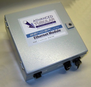
| − | The module connects any bender or measuring center devices through your Ethernet network to a bender that normally connects using only standard RS-232 signals. It gives your bender or measuring center access to a virtual COM port anywhere on the network in your building. Distance limitations are removed with this protocol. We have WiFi (wireless) and WIRED TCP/IP models. | + | The module connects any bender or measuring center devices through your Ethernet network to a bender that normally connects using only standard RS-232 signals. It gives your bender or measuring center access to a virtual COM port anywhere on the network in your building. Distance limitations are removed with this protocol. We have WiFi (wireless) and WIRED TCP/IP models.<br><br> |
| + | The Eaton Leonard version of the module includes a current loop board that we designed and improved for the Eaton Leonard Current Loop protocol. | ||
</td> | </td> | ||
<td> | <td> | ||
[[image:Wifi_logo.jpg]] | [[image:Wifi_logo.jpg]] | ||
| + | </td> | ||
| + | </tr> | ||
| + | </table> | ||
| + | |||
| + | ===Connect VTube-LASER to Eaton Leonard Premier Benders using Current Loop Electronics=== | ||
| + | <table> | ||
| + | <tr> | ||
| + | <td width=300> | ||
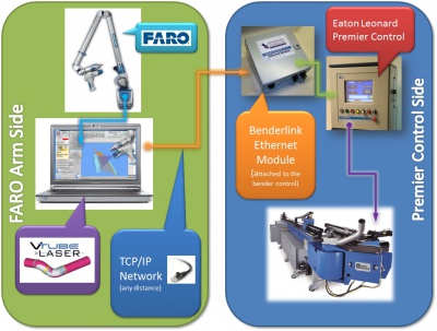
| + | The module, equipped with our current loop electronics, can be used to connect the [[FARO]] arm with [[VTube-LASER]] software to [[Eaton Leonard]] benders.<br><br> | ||
| + | For how VTube-LASER COMMUNICATES with EL benders, see the [[VTube-LASER to Eaton Leonard Premier Communications Tutorial]].<br><br> | ||
| + | For how VTube handles the date internally, see [[VTube-LASER Data Handling for Premier, EL2000, and Velog Controls]]. | ||
| + | </td> | ||
| + | <td> | ||
| + | [[image:diagram_vtube_to_premier.jpg|400px]] | ||
</td> | </td> | ||
</tr> | </tr> | ||
| Line 28: | Line 44: | ||
</table> | </table> | ||
| − | === | + | ===Cabling=== |
| + | |||
<table> | <table> | ||
<tr> | <tr> | ||
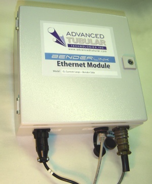
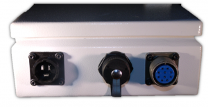
| − | <td width=300> | + | <td width=300>This is a module with cables in place. Three cables are attached to the wired version. A fourth wireless antenna cable is attached for wireless version.<br><br> |
| − | + | # The Power Supply port is on the left. | |
| + | # The Ethernet port is in the middle. | ||
| + | # The Current loop port is on the right. | ||
</td> | </td> | ||
<td> | <td> | ||
| − | [[image: | + | [[image:blink_ethernet_module_vector_benderside_cables_600.jpg|300px]]<br><br> |
| + | [[image:BenderlinkEternetModuleEL_Ports.png|300px]] | ||
</td> | </td> | ||
</tr> | </tr> | ||
| + | |||
</table> | </table> | ||
| − | === | + | ===PINES TS-2000 to Eaton Leonard Tube Data Center=== |
<table> | <table> | ||
<tr> | <tr> | ||
<td width=300> | <td width=300> | ||
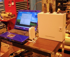
| − | + | This is a single port Benderlink Ethernet Module that connected a TS-2000 (Pines) control to an Eaton Leonard Vector 1 measuring center. | |
</td> | </td> | ||
<td> | <td> | ||
| − | [[image: | + | [[image:Blink_module_vector_test1.jpg|300px]] |
| + | </td> | ||
| + | </tr> | ||
| + | <tr> | ||
| + | <td width=300 valign=top> | ||
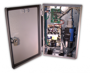
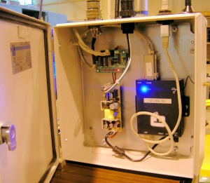
| + | This is the internal setup.<br><br> | ||
| + | *The Current Loop board is in the upper left corner.<br><br> | ||
| + | *The Ethernet Serial Device Server is the black box on the right.<br><br> | ||
| + | *The power supply is on the lower left. | ||
| + | </td> | ||
| + | <td> | ||
| + | [[image:Blink_module_vector_test3.jpg|300px]]<br><br> | ||
</td> | </td> | ||
</tr> | </tr> | ||
</table> | </table> | ||
| + | ===Module for EL Vector Laservision to Benderlink for COMCO=== | ||
| + | <table> | ||
| + | <tr> | ||
| + | <td width=300> | ||
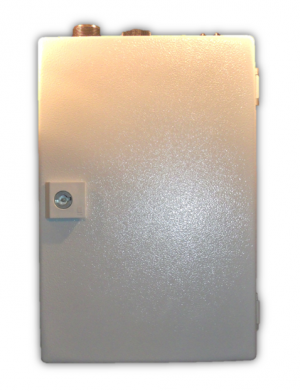
| + | This is the newer and more compact version of the Benderlink Ethernet Module that is designed for connection to an Eaton Leonard Vector Laservision measuring center for conversion through Benderlink for COMCO. | ||
| + | </td> | ||
| + | <td> | ||
| + | [[image:BenderlinkEternetModuleEL_External1.png|300px]] | ||
| + | </td> | ||
| + | </tr> | ||
| − | |||
<tr> | <tr> | ||
| − | <td width= | + | <td width=300 valign=top> |
| + | This is internal setup.<br><br> | ||
| + | *The Current Loop board is in the upper left corner.<br><br> | ||
| + | *The Ethernet Serial Device Server is the black box on the right.<br><br> | ||
| + | *The larger (and much improved) power supply is on the lower left. | ||
</td> | </td> | ||
<td> | <td> | ||
| − | [[image: | + | [[image:BenderlinkEternetModuleEL_Internal2.png|300px]] |
</td> | </td> | ||
</tr> | </tr> | ||
| Line 65: | Line 110: | ||
</table> | </table> | ||
| − | ===Other | + | <br><br> |
| + | |||
| + | ===Other Applications=== | ||
{| border="0" cellpadding="10" cellspacing="0" align="none" width=500 | {| border="0" cellpadding="10" cellspacing="0" align="none" width=500 | ||
| Line 71: | Line 118: | ||
! style="background:#b3b0c8;" | Bender | ! style="background:#b3b0c8;" | Bender | ||
! colspan="2" style="background:#acbcce;" | Description | ! colspan="2" style="background:#acbcce;" | Description | ||
| + | |- | ||
| + | | SMT Bender | ||
| + | | We use a Benderlink Module to make the SMT act like a Premiere bender control to an Eaton Leonard Vector measuring center. | ||
|- | |- | ||
| PINES TS-2000 | | PINES TS-2000 | ||
| Line 89: | Line 139: | ||
| MiiC | | MiiC | ||
| Works with a MiiC to place it on the network (See [[Benderlink for MiiC]]) | | Works with a MiiC to place it on the network (See [[Benderlink for MiiC]]) | ||
| + | |- | ||
| + | | YLM | ||
| + | | Works with a YLM to connect to an EL Vector Laservision Measureing Center (See [[Benderlink for YLM]]) | ||
| + | |- | ||
| + | | COMCO | ||
| + | | Works with a COMCO to connect to an EL Vector Laservision (See [[Benderlink for COMCO]]) | ||
|} | |} | ||
| Line 103: | Line 159: | ||
<br><br> | <br><br> | ||
| − | [http://www.advancedtubular.com/ | + | [http://www.advancedtubular.com/blink_keinschiyoda/blinkchi_module_datasheet.pdf Download a DataSheet] for Benderlink Ethernet Module for |
| − | Chiyoda | + | Chiyoda and KEINS |
<br><br> | <br><br> | ||
| Line 114: | Line 170: | ||
</table> | </table> | ||
| − | + | ==Tutorials and Information== | |
| − | + | * See [[How to Install a MOXA Device Driver in Windows]] | |
==Other Pages== | ==Other Pages== | ||
Latest revision as of 17:27, 2 December 2016
Modules Add Serial Ports for Benders through NETWORKs
|
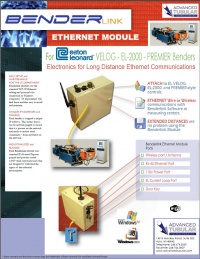
The module connects any bender or measuring center devices through your Ethernet network to a bender that normally connects using only standard RS-232 signals. It gives your bender or measuring center access to a virtual COM port anywhere on the network in your building. Distance limitations are removed with this protocol. We have WiFi (wireless) and WIRED TCP/IP models. |
Connect VTube-LASER to Eaton Leonard Premier Benders using Current Loop Electronics
|
The module, equipped with our current loop electronics, can be used to connect the FARO arm with VTube-LASER software to Eaton Leonard benders. |
Connect to EL Vector Tube Data Centers Using Current Loop Electronics
|
The module can even be equipped with our version of the Eaton Leonard current loop boards (our own model called the CB-EL1) to allow for 100% compatible Eaton Leonard legacy protocol through the network for connection to an EL Vector Tube Data Center |
Cabling
This is a module with cables in place. Three cables are attached to the wired version. A fourth wireless antenna cable is attached for wireless version.
|
PINES TS-2000 to Eaton Leonard Tube Data Center
|
This is a single port Benderlink Ethernet Module that connected a TS-2000 (Pines) control to an Eaton Leonard Vector 1 measuring center. |
|
|
This is the internal setup.
|
Module for EL Vector Laservision to Benderlink for COMCO
|
This is the newer and more compact version of the Benderlink Ethernet Module that is designed for connection to an Eaton Leonard Vector Laservision measuring center for conversion through Benderlink for COMCO. |
|
|
This is internal setup.
|
Other Applications
| Bender | Description | |
|---|---|---|
| SMT Bender | We use a Benderlink Module to make the SMT act like a Premiere bender control to an Eaton Leonard Vector measuring center. | |
| PINES TS-2000 | Using Benderlink for Pines - Add a module to a Vector Tube Data Center to enable a network connection through a current-loop module directly into the standard Vector bender port. | |
| BLM VGP | Using Benderlink for BLM - Add a module to Vector Tube Data Center to enable a network connection through a current-loop module directly into the standard Vector bender port. | |
| ROMER to Eaton Leonard Bender | Add a module to any Eaton Leonard bender and make it wireless. | |
| CHIYODA | Add this module to a Chiyoda to allow it to communicate over the network from its RS-232 port. | |
| KEINS | Add this module to a KEINS to allow it to communicate over the network from its RS-232 port. | |
| MiiC | Works with a MiiC to place it on the network (See Benderlink for MiiC) | |
| YLM | Works with a YLM to connect to an EL Vector Laservision Measureing Center (See Benderlink for YLM) | |
| COMCO | Works with a COMCO to connect to an EL Vector Laservision (See Benderlink for COMCO) | |
PDF DataSheets
|
Download a DataSheet for Benderlink Ethernet Module for Eaton Leonard
|
